PC800, 850-8 9
30 Testing and adjusting SEN00786-02
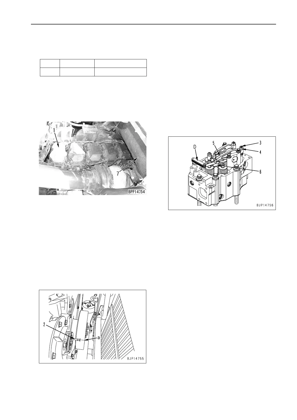
Adjusting valve clearance
a Adjusting tools for valve clearance
1. Remove the engine hood assembly and muffler
(7).
4 Engine hood assembly: 340 kg
2. Remove all cylinder head covers (1).
3. Rotate the crankshaft in the normal direction to
align [1.6 TOP] line (a) on the damper with
pointer (2), and set the No.1 cylinder compres-
sion to top dead center.
a Check the pointer from the alternator side.
a Crank the engine with the hexagonal part at
the water pump drive shaft on the alternator
side.
a At the compression top dead center, the
rocker arm of the No. 1 cylinder can be
moved by hand an amount equal to the valve
clearance. If the rocker arm does not move,
it is not at the compression top dead center,
so rotate the crankshaft one more turn.
4. Insert clearance gauge D in clearance (b)
between rocker arm (5) and crosshead (6), and
turn adjustment screw (3) to adjust the valve
clearance.
a With clearance gauge D inserted, turn the
adjustment screw and adjust until the clear-
ance is a sliding fit.
a Valve clearance:
Intake valve: 0.35 mm, Exhaust valve: 0.57 mm
5. Tighten locknut (4) to hold adjustment screw (3)
in position.
3 Locknut:
45.1 – 51.0 Nm {4.6 – 5.2 kgm}
a After tightening the locknut, check the valve
clearance again.
6. Rotate the crankshaft 120° each time in the nor-
mal direction and repeat Steps 2 - 4 to adjust the
valve clearance of each cylinder according to
the firing order.
a Firing order: 1-5-3-6-2-4
7. After completing the adjustment, set to the origi-
nal condition.
3 Mounting bolt of cylinder head cover:
29.4 – 34.3 Nm {3.0 – 3.5 kgm}
Symbol Part No. Part Name
D Purchased Clearance gauge
 Loading...