44 PC800, 850-8
SEN00790-02 40 Troubleshooting
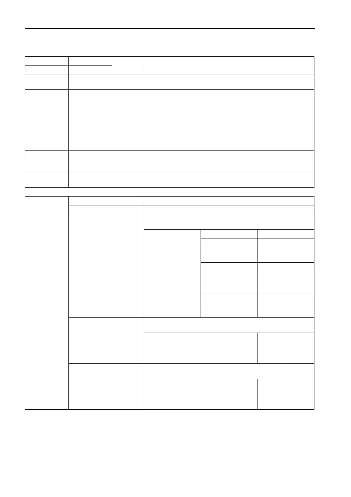
Failure code [CA227] Sens Supply 2 Volt High Error
* Connector “PEVA” is not applied to the following machines:
• PC800-8: 55001 and up
• PC850-8: 10007, 55001 and up
Action code Failure code
Trouble
Sens Supply 2 Volt High Error
(Engine controller system)
E15 CA227
Contents of
trouble
• High voltage error occurred in sensor power supply 2 (5V) circuit.
Action of
controller
• Engine Bkup speed sensor operates with signal from engine Ne speed sensor.
• Oil pressure sensor sets oil pressure to default (250 kPa {2.5 kg/cm
2
}) and continues operation.
• Ambient pressure sensor sets ambient pressure to default (52.44 kPa {0.53 kg/cm
2
}) and continues
operation.
• Charge air pressure sensor fixes charge pressure at 400 kPa {4.1 kg/cm
2
} and continues operation.
• EGR inlet pressure sensor sets EGR inlet pressure to default (102 kPa {1.0 kg/cm
2
}) and continues
operation.
• EGR valve lift sensor limits output, and closes EGR and bypass valves.
• Bypass valve lift sensor limits output, and closes EGR and bypass valves.
Problem that
appears on
machine
• Engine output lowers.
Related
information
Possible causes
and standard
value in normal
state
Cause Standard value in normal state/Remarks on troubleshooting
1 Defect in related system If another failure code is displayed, carry out troubleshooting for it.
2
Defective sensor
(Internal defect)
aPrepare with starting switch OFF, then turn starting switch ON and
carry out troubleshooting.
Disconnect sensors at
right in order. If no
error code is displayed,
that sensor is defec-
tive.
Bkup Speed Sensor G connector
Oil pressure sensor POIL connector
Ambient pressure sen-
sor
PAMB connector
Charge air pressure
sensor
PIM connector
EGR inlet pressure
sensor
PEVA connector
EGR valve lift sensor SEGR connector
Bypass valve lift sen-
sor
SBP connector
3
Disconnection in wiring
harness
(Disconnection in wiring or
defective contact in con-
nector)
aPrepare with starting switch OFF, then carry out troubleshooting with-
out turning starting switch ON.
Wiring harness between ENG (female) (37) –
each sensor (female)
Resis-
tance
Max. 1 z
Wiring harness between ENG (female) (47) –
each sensor (female)
Resis-
tance
Max. 1 z
4
Ground fault in wiring har-
ness
(Short circuit with GND cir-
cuit)
aPrepare with starting switch OFF, then carry out troubleshooting with-
out turning starting switch ON.
Wiring harness between ENG (female) (37) –
each sensor (female) and chassis ground
Resis-
tance
Min. 1 Mz
Wiring harness between ENG (female) (47) –
each sensor (female) and chassis ground
Resis-
tance
Min. 1 Mz
 Loading...