Installation
1 12345678910111213141516
© 2022 KOSTAL Solar Electric GmbH48
4.6Electrical connection
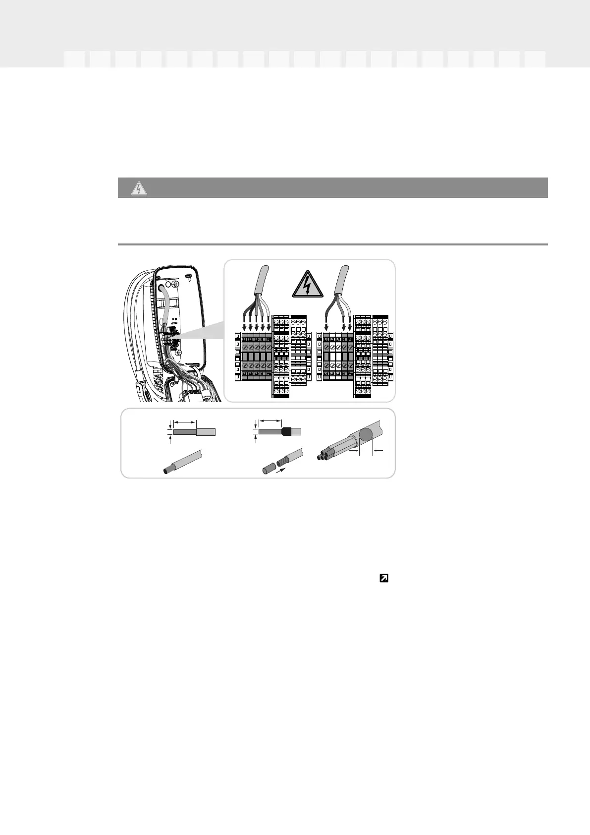
The wallbox may be connected to a TN / TT grid.
DANGER
Risk of death due to electrical shock and discharge!
De-energise device and secure against being switched on again.
AC
3 ph~
L2L1L3NPE
max. 10-17 mm
10 mm10 mm
2,5-6 mm²
NYM-J
NYY-J
4 mm²
H05../H07
RN-F
AC
1 ph~
L1NPE
1.Strip the supply cable.
2.Strip 10 mm of insulation from the wires.
3.Connect the wires to the terminals according to the terminal labelling.
Three-phase operation: Use terminals L1, L2, L3, N and PE.
Single-phase operation: Use terminals L1, N and PE.
Observe the connection data for the terminal strip
Technical data,Page94.
4.Check that the individual wires are connected correctly and that the screws are
tightened securely.
✔ Supply cable connected.