Connection of additional components
1 12345678910111213141516
© 2022 KOSTAL Solar Electric GmbH51
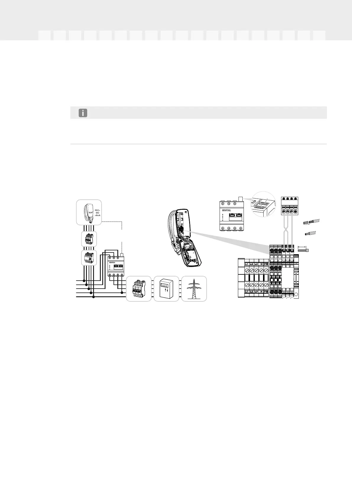
For cable inlet on the rear: Use membrane cable entries without strain relief.
Insert the cables into the wallbox. To do this, a hole must be pierced in the mem-
brane.
NOTE
To prevent rainwater from entering, the hole in the membrane should not be any larger
than the cables.
5.Strip the cable.
6.Strip 10mm of insulation from the wires.
7.Connect communication cable to wallbox terminal according to the terminal labelling.
B
GND
A
4 3 2 1
RS485 (B)
Cat 6
RS485
Modbus
LAN
L1 L2 L3
L1 L2 L3 N
LAN
STATUS
NETWORK
SERIAL BUS
REST
Smart Energy Meter
A
B
max. 30 m
0,5-1,5 mm²
0,5-1,5 mm²
B
GND
A
RS485
10 mm
Wallbox
RS485
Modbus RTU
RS485
Modbus
LAN
L1 L2 L3
L1 L2 L3 N
LAN
STATUS
NETWORK
SERIAL BUS
REST
Smart Energy Meter
8.Connect communication cable to energy meter.
✔ Connect wallbox with energy meter.