FC-18 – Defining FC-18 Display Controller
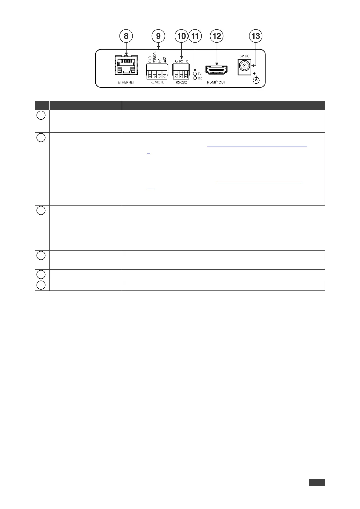
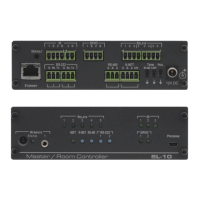
Figure 2: FC-18 Display Controller Rear Panel
Connect to a PC via a LAN to control the device, send commands to the
display, or tunnel RS-232 data to the display. Also use for firmware
upgrade.
REMOTE 4-pin Terminal
Block Connector
Connect to contact closure switches (by momentary contact between the
desired pin and GND pin), see Connecting Remote Control Switches
on page 8.
TOGGLE – one button toggles between display ON and display OFF
(instead of using two separate buttons for ON and OFF). The button can
be set for edge triggering (momentary connection) or for level triggering
(constant contact connection), see Setting the Toggle Pin Function
on page 45.
ON – turns the display on.
OFF – turns the display off.
RS-232 3-pin Terminal
Block Connectors
(G, Rx, Tx)
Set the function of the RS-232 port via the webpages:
Connect to the display to send RS-232 commands to the display (default)
via web pages, for example.
OR
Connect to a PC or remote controller to control FC-18 (for example,
instructing it to send a CEC command to turn the display on or off).
Lights red when RS-232 port transmits data.
Lights green when RS-232 Port receives data.
Connect to a CEC enabled HDMI acceptor.
Connect to the supplied power adapter.