ADD FURNACE CO.,LTD.
44 ซอยบรมราชชนนี
โทร: 02-888-3472 โทร: ออกแบบ:08-08-170-170 แฟกซ์: 02-888-3258
https://www.add-furnace.com E-mail: sales@add-furnace.com
Contents
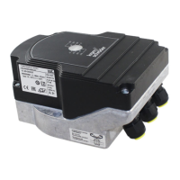
Actuators IC 20, IC 40 . . . . . . . . . . . . . . . . . . . . . . . . . . . . . . . . . . . . . 1
Contents . . . . . . . . . . . . . . . . . . . . . . . . . . . . . . . . . . . . . . . . . . . . . .. .2
1 Application . . . . . . . . . . . . . . . . . . . . . . . . . . . . . . . . . . . . . . . . . . . .4
1.1 Examples of application. . . . . . . . . . . . . . . . . . . . . . . . . . . . . . . . . . . ..7
1.1.1 IC 20, continuous control. . . . . . . . . . . . . . . . . . . . . . . . . . . . . . . . . .7
1.1.2 IC 20..E, continuous control . . . . . . . . . . . . . . . . . . . . . . . . . . . . . . . 7
1.1.3 IC 20, modulating control with burner control unit BCU 370 . . . . 8
1.1.4 IC 40, staged control. . . . . . . . . . . . . . . . . . . . . . . . . . . . . . . . . . . 9
1.1.5 IC 40, staged control with three burner capacity levels. . . . . . . 9
1.1.6 IC 40, continuous control by three-point step signal . . . . . . . . . 10
1.1.7 IC 40, staged control with pre-purge. . . . . . . . . . . . . . . . . . . . . . 11
1.1.8 IC 40, continuous control with defined ignition position. . . . . . 12
1.1.9 IC 40, hot-air compensation. . . . . . . . . . . . . . . . . . . . . . . . . . . . 13
1.1.10 IC 40, staged control with online adjustment of the
burner capacity. . . . . . . . . . . . . . . . . . . . . . . . . . . . . . . . . . . . . . . . 14
2 Certification . . . . . . . . . . . . . . . . . . . . . . . . . . . . . . . . . . . . . .. . . 15
3 IC 20 function . . . . . . . . . . . . . . . . . . . . . . . . . . . . . . . . . . . .. . . . 16
3.1 IC 20..T Connection diagram . . . . . . . . . . . . . . . . . . . . . . . . . . . . . 17
3.2 IC 20..E connection diagram . . . . . . . . . . . . . . . . . . . . . . . . . . . . . 18
3.2.1 Continuous control. . . . . . . . . . . . . . . . . . . . . . . . . . . . . . . . . . . . 18
3.2.2 2-point step control. . . . . . . . . . . . . . . . . . . . . . . . . . . . . . . . . . . . . 18
3.3 IC 20..E Display . . . . . . . . . . . . . . . . . . . . . . . . . . . . . . . . . . . . . . . . . 19
3.3.1 In Manual mode. . . . . . . . . . . . . . . . . . . . . . . . . . . . . . . . . . . . . . . 19
3.3.2 Low-fire/High-fire rate adjustment (in Manual mode
only) . . . . . . . . . . . . . . . . . . . . . . . . . . . . . . . . . . . . . . . . . . . . . . . . . . . . . . 19
3.3.3 Warnings and faults . . . . . . . . . . . . . . . . . . . . . . . . . . . . . .. . . .. . . 19
3.4 IC 20..E DIP switch. . . . . . . . . . . . . . . . . . . . . . . . . . . . . . . . . ... . . ... 20
4 IC 40 function . . . . . . . . . . . . . . . . . . . . . . . . . . . . . . . . . . . . . . . . 21
4.1 Operating modes. . . . . . . . . . . . . . . . . . . . . . . . . . . . . . . . . .. . . . . .22
4.2 Standard and analogue operating modes. . . . . . . . . . .. . . . . . . . 22
4.3 Closed, low-fire rate, intermediate and open position . . . . . . .. 22
4.4 Running times. . . . . . . . . . . . . . . . . . . . . . . . . . . . . . . . . . . . . . . . . . . 23
4.5 Standard operating modes 1 – 12. . . . . . . . . . . . . . . . . . . . . . . .. . 24
4.5.1 2-point operation. . . . . . . . . . . . . . . . . . . . . . . . . . . . . . . . . . . . .... 24
4.5.2 2-point operation with flame proving period . . . . . . . . . . . . . ..... 25
4.5.3 2-step operation with one or two digital inputs . . . . . . . . . .
...
. 26
4.5.4 2-step operation with two digital inputs . . . . . . . . . . . . . . . . . . . . 28
4.5.5 3-point step operation. . . . . . . . . . . . . . . . . . . . . . . . . . . . . . . . . . 29
4.5.6 3-step operation with one or two digital inputs . . . . . . . . . . . . . . 30
4.5.7 2-point operation with switchover of the adjustment
angle for the “open” position. . . . . . . . . . . . . . . . . . . . . . . . . . . . . . . . . 32
4.5.8 2-point operation with input-dependent adjustment
angle for the “open” position. . . . . . . . . . . . . . . . . . . . . . . . . . . . . . . . . . . 34
4.5.9 2-point operation with switchover of the running times. . . . . . . . . .35
4.5.10 3-point step operation with running time fractions. . . . . . . . . . . . 36
4.5.11 3-step operation with two digital inputs . . . . . . . . . . . . . . . . . . . . . 38
4.5.12 3-point step operation with low position . . . . . . . . . . . . . . . . . . . . .39
4.6 Analogue operating modes 21 – 27. . . . . . . . . . . . . . . . . . . . . . . . . . .40
4.6.1 2-point operation . . . . . . . . . . . . . . . . . . . . . . . . . . . . . . . . . . . . . . . . .40
4.6.2 2-point operation with switchover of the adjustment
angle for the “open” position. . . . . . . . . . . . . . . . . . . . . . . . . . . . . . . . . . .42
4.6.3 2-point operation with input-dependent adjustment
angle for the “open” position. . . . . . . . . . . . . . . . . . . . . . . . . . . . . . . . . . . 44
4.6.4 2-point operation with switchover of the running times. . . . . . . . . .45
4.6.5 2-point operation with characteristic curve switchover I . . . . . . . .47
4.6.6 2-point operation with characteristic curve switchover II . . . . . . . 49
4.6.7 2-step operation with two digital inputs and variable
adjustment angl . . . . . . . . . . . . . . . . . . . . . . . . . . . . . . . . . . . . . . . . . . . . . .51
4.6.8 Safety closing function. . . . . . . . . . . . . . . . . . . . . . . . . . . . . . . . . . . . .52
4.7 Parameters . . . . . . . . . . . . . . . . . . . . . . . . . . . . . . . . . . . . . . . . . . . . . . . 53
4.7.1 Parameter sets . . . . . . . . . . . . . . . . . . . . . . . . . . . . . . . . . . . . . . . . . . .54
4.7.2 Factory default parameters. . . . . . . . . . . . . . . . . . . . . . . . . . . . . . . . 56
4.8 Inputs. . . . . . . . . . . . . . . . . . . . . . . . . . . . . . . . . . . . . . . . . . . . . . . . . . . . .57
4.8.1 Digital . . . . . . . . . . . . . . . . . . . . . . . . . . . . . . . . . . . . . . . . . . . . . . . . . . 57
4.8.2 Analogue . . . . . . . . . . . . . . . . . . . . . . . . . . . . . . . . . . . . . . . . . . . . . . . 57
4.9 Outputs . . . . . . . . . . . . . . . . . . . . . . . . . . . . . . . . . . . . . . . . . . . . . . . . . . 59
4.10 Manual mode . . . . . . . . . . . . . . . . . . . . . . . . . . . . . . . . . . . . . . . . . . . .60
4.10.1 Direct position preset . . . . . . . . . . . . . . . . . . . . . . . . . . . . . . . . . . . . 60
4.10.2 Simulate inputs. . . . . . . . . . . . . . . . . . . . . . . . . . . . . . . . . . . . . . . . . . 60
4.11 Statistics. . . . . . . . . . . . . . . . . . . . . . . . . . . . . . . . . . . . . . . . . . . . . . . . . .61
4.11.1 Counters. . . . . . . . . . . . . . . . . . . . . . . . . . . . . . . . . . . . . . . . . . . . . . . 61
4.11.2 Measured values . . . . . . . . . . . . . . . . . . . . . . . . . . . . . . . . . . . . . . . .61
4.11.3 Resetting statistics. . . . . . . . . . . . . . . . . . . . . . . . . . . . . . . . . . . . . . . 61
4.11.4 Resetting a signal . . . . . . . . . . . . . . . . . . . . . . . . . . . . . . . . . . . . . . . 61
4.12 IC 40 connection diagram . . . . . . . . . . . . . . . . . . . . . . . . . . . . . . . . . 62
4.13 Display . . . . . . . . . . . . . . . . . . . . . . . . . . . . . . . . . . . . . . . . . . . . . . . . . . 63
4.13.1 During operation. . . . . . . . . . . . . . . . . . . . . . . . . . . . . . . . . . . . . . . . 63
4.13.2 Warnings and faults. . . . . . . . . . . . . . . . . . . . . . . . . . . . . . . . . . . . . . 63
4.14 Relay outputs RO 1 and RO 2 function .. . . . . . . . . . . . . . . . . . . . . . .65
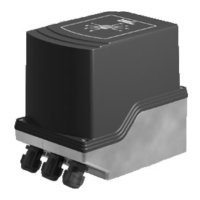
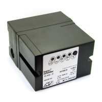
5 Replacement possibilities for actuators . . . . . . . . . . . . . . . . . . . . . . . . .66