ADD FURNACE CO.,LTD.
44 ซอยบรมราชชนนี
โทร: 02-888-3472 โทร: ออกแบบ:08-08-170-170 แฟกซ์: 02-888-3258
https://www.add-furnace.com E-mail: sales@add-furnace.com
7 Project planning information
7.1 Electrical connection
7.1.1 Cable selection
Install supply and signal lines separately.
Cables should be installed well away from high-voltage
lines
of other devices.
Observe EMC Directive for installation of signal lines.
7.1.2 IC 20
When operating two or more actuators in parallel, they
must
be electrically isolated to avoid leakage currents.
7.1.3 IC 20..E
Position feedback at terminals 15 and 16:
Any interference suppression capacitors installed in the
system
must only be used in conjunction with a series resistor so
as not to exceed the -maximum switch-on current, see
page
76 (Technical data).
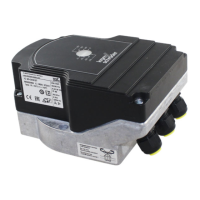
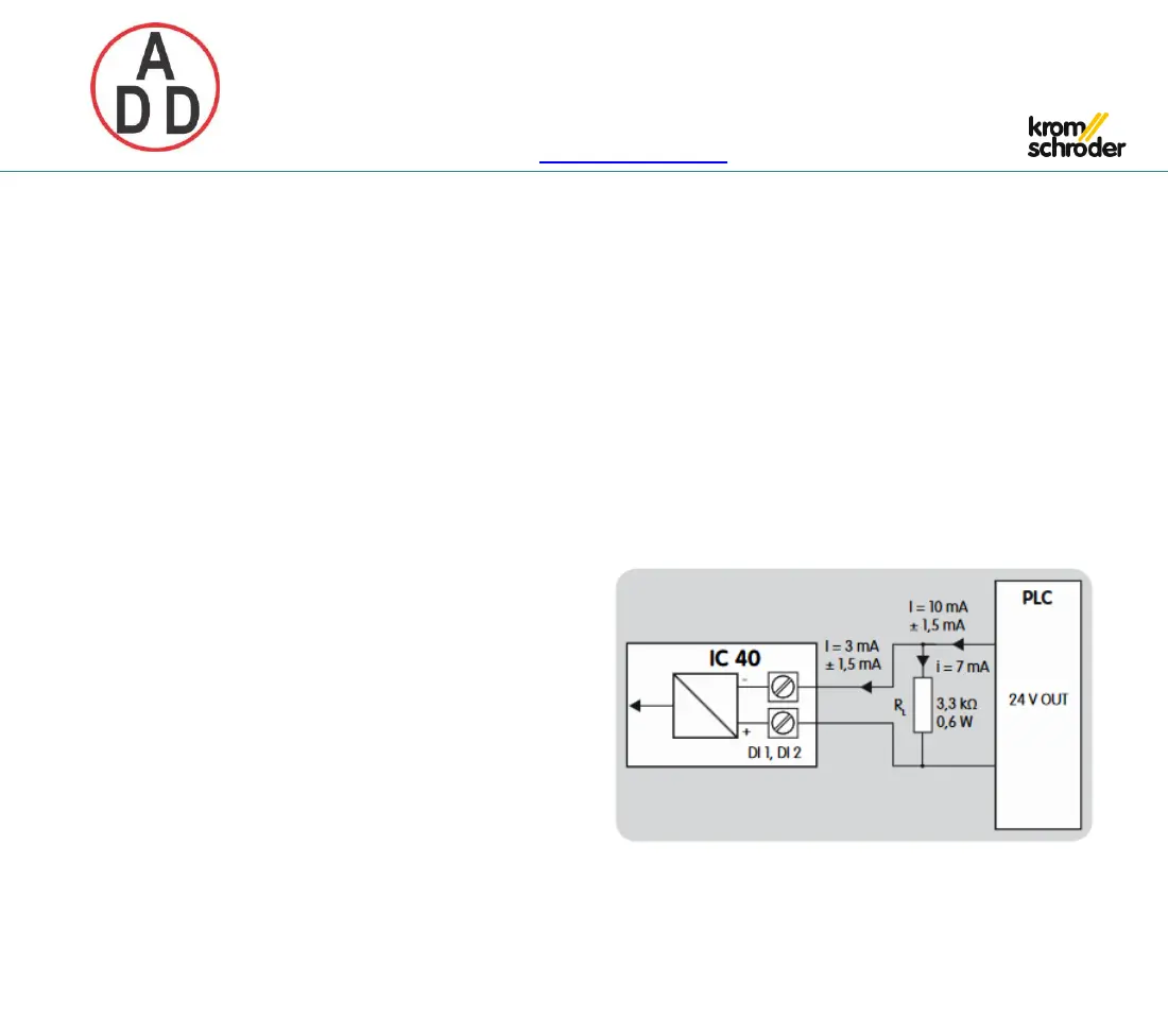
7.1.4 IC 40
Digital inputs
The digital inputs require a current of 3 mA ±1.5 mA. To
avoid
interference, it may be necessary to increase the output
current
by using an additional load resistor on the signal sensor.
Load resistors may not be fitted inside the IC 40 for
reasons
relating to heat dissipation.
Example for 24 V DC and 10 mA:
Load resistor = 3.3 kΩ, 0.6 W.