ADD FURNACE CO.,LTD.
44 ซอยบรมราชชนนี
โทร: 02-888-3472 โทร: ออกแบบ:08-08-170-170 แฟกซ์: 02-888-3258
https://www.add-furnace.com E-mail: sales@add-furnace.com
Technical data
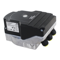
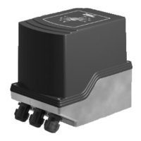
9.2 IC 40
Mains voltage:
IC 40: 100 – 230 V AC, ±10%, 50/60 Hz; the actuator
auto-matically adjusts to the respective mains voltage.
Power consumption: 8.4 W,
switch-on peak current: max. 8 A for max. 10 ms.
Screw terminals using the elevator principles for cables
up to 4 mm
2
(single core cables) and for cables up to 2.5
mm
2
with wire end ferrules.
Angle of rotation: 0 – 90°.
Holding torque = torque as long as permanent supply
volt-age is applied.
2 digital inputs:
IC 40: 24 V DC or 100 – 230 V AC each.
Current requirement of digital inputs: 3 mA ± 1.5 mA.
1 analogue input (optional): 4 – 20 mA (internal load
imped-
ance: max. 500 Ω at 20 mA).
Potentiometer (optional):
1000 Ω +/- 20%,
linearity tolerance +/- 2%,
max. capacity 0.25 W,
conductive plastic element.
Important: tap wiper at high resistance, see page
70 (Project planning information)
2 digital outputs:
Signalling contacts designed as relay change-over
contacts. Contact current of digital outputs: min. 5 mA
(resistive) and max. 2 A.
The relay contacts can be connected to 100 – 230 V AC
or
24 V DC. If the contacts have been connected with a
volt-age > 24 V and a current > 0.1 A once, the gold
plating on
the contacts will have been burnt through. This contact
can then only be connected with this power rating or
higher power rating.
2 LED status displays:
– Blue LED for operation “ON”;
drive in motion = slow flashing light;
manual operation = fast flashing
light; drive stopped = permanent
light.
– Red LED for warnings and
faults; warning = permanent
light; fault = flashing light.
– Red and blue LED simultaneously,
calibration in progress = flashing
light.
Enclosure: IP 65 pursuant to IEC 529.
Safety class: I pursuant to EN 60335.
Line entrance for electrical connection:
3 × M20 plastic cable glands.
Ambient temperature: -20 to +60°C, no condensation
per-mitted.