RWCP, RWCN
10
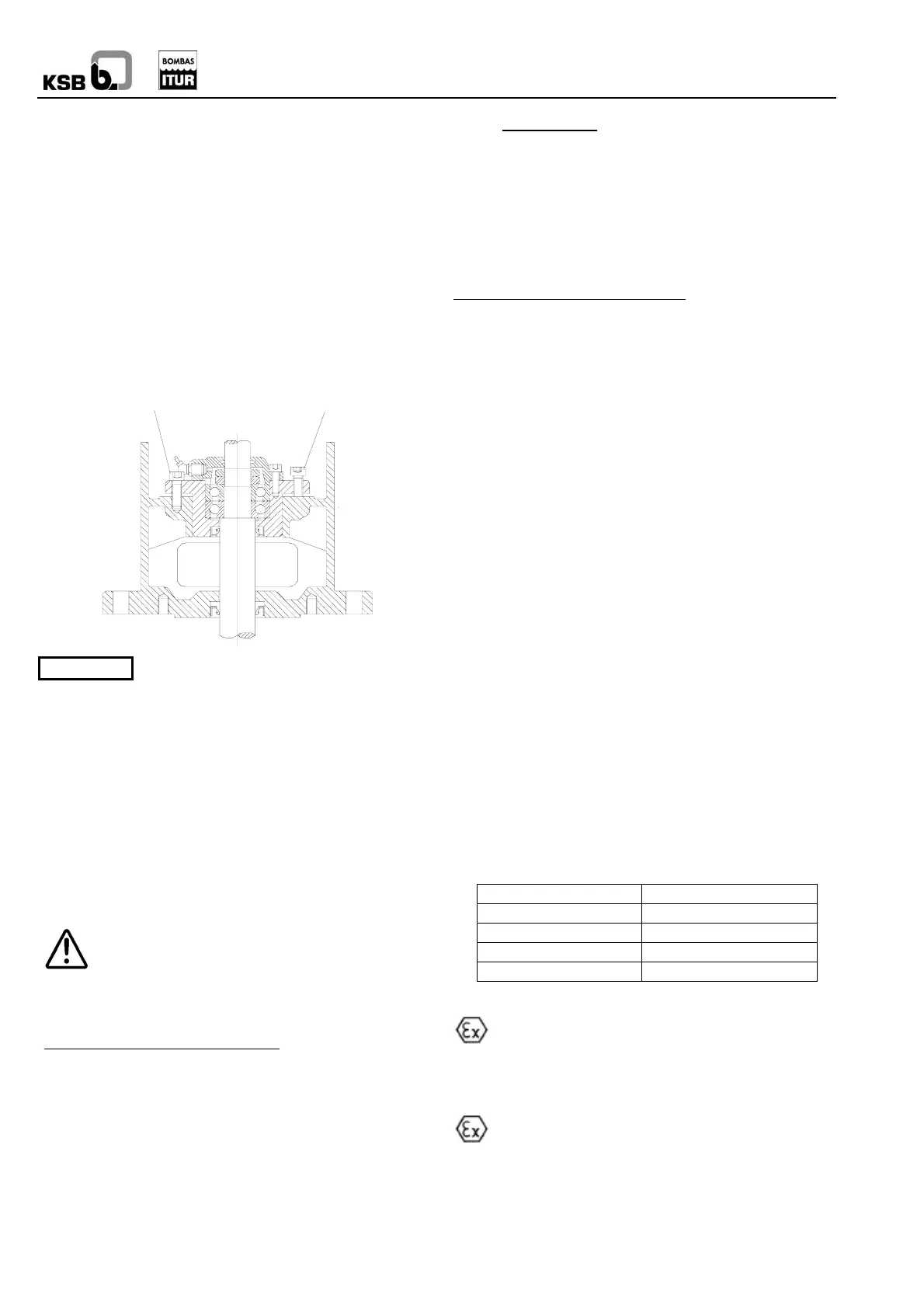
6.1.4 Impeller adjustment
Turn the pump shaft by hand to check that the rotor is not
blocked. Should interior contact in the pump be detected,
carry out an axial regulation. To do this:
- Release the attachment screws (2)
- Tighten the adjusting screws (1) to slightly raise the
whole moving section.
- Turn the shaft again by hand and check that the rotor
rotates freely without any internal contact. If there
continues to be contact, tighten a little more using the
adjusting screws.
- Tighten the attachment screws (2) to fix the position
reached.
2
If a mechanical seal is used, remove it first
before regulating. Please contact us before
carrying out this operation.
6.1.5 Start-up
Before starting up the group, check all the sections with
regards to chapter 6.
The start-up must be carried out with the suction valve (where
fitted) completely open and the impulsion valve partially
closed. Once the pump has reached its service speed and the
suction air has been eliminated, regulate the operation point
using the impulsion valve.
If the electric motor guard is triggered when starting up, close
the impulsion valve more until the equipment starts up
normally.
The pump must NEVER work with zero flow or flow
which is less than the operating minimum, as internal
recirculation will cause the fluid to heat up quickly,
leading to hazards (including explosion) as a result of the high
pressures reached within the frame. Check the minimum flow
in the operation curves.
Minimum flow necessary for the pump
The pumps cannot work below the minimum flow specified in
the datasheets.
If this condition may come about, the installation must be fitted
with safety devices which prevent the operation of the pump
without liquid inside, or have automatic devices to discharge
the minimum flow of the pump.
For liquids other than water, the minimum flow is determined
by the following formula:
Qmin =
3.600.000 x Pa
Pe x Ce
In which:
Qmin: Minimum flow in m
3
/h.
Pa: Power absorbed by the pump in kW at closed valve.
Ce: Specific heat of the fluid in J/kg*ºC.
Pe: Specific weight of the fluid in kg/m
3
Maximum flow permitted by the pump
Unless indicated in another datasheet, the maximum flow
permitted is 1.1x optimum flow of the pump with the supplied
impeller diameter.
6.1.6 Shutdown
Close the impulsion pipe valve.
If there is anti-return in impulsion with counter pressure, leave
the impulsion valve open.
- Shutdown the motor. Check that shutdown is normal.
- In prolonged periods of non-operation, close the suction
pipe valve (where fitted) and the auxiliary connection
valves.
- The pump must be protected from freezing whenever this
risk exists, and must be emptied in prolonged periods of
non-operation.
If, whilst the pump is in standstill, it must remain on standby
for service, start up at regular intervals for around 5 minutes
(see also 7.2.1)
- Fire pumps: 1x/month, at minimum.
- Drink-safe water pumps: 1x/48 hours, at minimum.
Note
- Reserve pumps: 1x/week, at minimum.
(It is best to change the operating pump every day).
The seal tightness and function of the auxiliary connections
must be examined during these start-ups.
6.2 Service limits
6.2.1 Switching frequency
In order to prevent abnormally high temperatures and
overloading of the motor, pump, coupling, seals, etc, the
switching frequencies must not be exceed the following
number of start-ups per hour:
MOTOR POWER MAX. SWITCHING/HOUR
Up to 3 kW 20
From 4 to 11 kW 15
From 11 to 45 kW 10
From 45 kW 5
6.2.2 Temperature of the liquid to be pumped
The permitted operation temperature is indicated in
the order and in the ATEX conformity declaration. If
the pump is to work at a higher temperature or you do not
have the data sheet, please ask KSB ITUR.
6.2.3 Density of the liquid to be pumped
The power absorbed by the pump increases in direct
proportion to the density of the impelled liquid. In order
to prevent overloading in the motor, pump and coupling, this
density must not exceed that shown in the order and in the
ATEX declaration of conformity.

 Loading...