RWCP, RWCN
8
pump suction, always aiming to achieve the most stable
flow possible.
- If several pumps are working in parallel in a single well,
they should be at a suitable distance from each other, or
precautions should be taken to ensure there is no
disturbance which may affect the suction conditions of
the pump.
The maximum liquid level must always be below the
base plate in order for it not to overflow.
Dry well. Suction conditions
In this type of installation we need to:
- In the pump suction, avoid sharp angle joints and
accessories which lead to brusque narrowing and
widening.
- Position a gate valve in the suction to isolate the pump
during maintenance.
- With a pipe, take the excess fluid of the column from the
orifice in the upper column through to an upper level at
the maximum water level of the suction tank or suitable
drainage system.
The minimum liquid level in the well in start-up must be a least
0.5 m above the pump suction flange, and must be maintained
at sufficient height as to avoid air coming in through suction
due to the vortex effect.
5.3.1 Auxiliary connections
The equipment is normally delivered mounted and ready for
immediate operation, with only the hydraulic and exterior
electrical connections being necessary.
In the case of dirty or abrasive pumping liquids in which it is
necessary to connect the auxiliary refrigeration connections or
lubrication of the equipment, follow the instructions detailed in
7.2.2 or in annexes to this manual.
Auxiliary pipes are designed exclusively to
support internal strains due to the pressure of
the circulating fluid, to which end it is forbidden to subject
them to additional exterior strains (e.g. leaning on them, etc).
If the pumping liquid is fuel and the leak can lead to
ignition, this contingency should be avoided through
constant control of the seal tightness of the auxiliary pipe
joints by the plant operator.
5.4 Electrical connection:
The electrical connection must be carried out by a
specialist electrician! Applicable regulations must be
complied with.
Check the mains voltage available with the factory plate data
and choose the appropriate connection.
The technical connection conditions and the conditions
of the local energy supply company must be observed
when carrying out the connections.
We strongly recommend the use of a safety circuit
breaker for the motor and a thermistor associated to a
trigger device.
These instructions apply to asynchronous three-phase
standard electric motors with a squirrel cage both in
horizontal and vertical execution, in IP-23, IP-54 and IP-55
protection grades, with frame sizes of between 56L and
355S, both inclusive, with voltages of 200 to 500 V
between phases
The electric motor as well as whole electric installation
shall accomplish with all safety norms that may be
applied to it.
Earthing
Before starting up the pump, the earth of the pump, the
baseplate or the motor must be connected to an effective
earthed point of the installation.
5.4.1 Motor connection
Whilst connecting the cables, ensure it is not possible
for voltage to appear.
Check that the earth connection is in line with local
regulations.
The coupling may produce a source of ignition or high
temperature in the event of incorrect operation. For
this reason, the motor must be classified with at least the
same type of zone and temperature as the pump. It is
necessary to follow the instructions in the coupling manual
which is included with the pump.
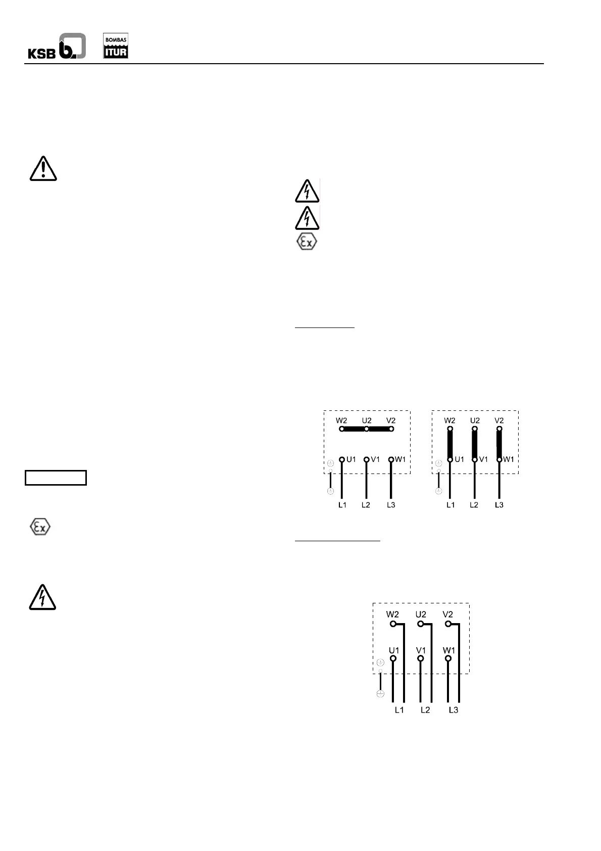
Connection in single speed motors
Direct start-up:
In direct start-up the motor can be used in two different
connections:
The voltage and the connection, e.g. 400 VY, 240 VD is
stamped on the motor plate. This means that the motor can
connect at 400 volts in star connection (Y) or at 240 volts in
triangle connection (D).
Note
Star connection Triangle connection
Star-triangle start-up:
In star-triangle start-up, the line voltage must coincide with the
voltage shown on the motor for triangle start up (D). The six
terminals indicated in the following diagram will be connected:
Connection to the star-triangle contactor