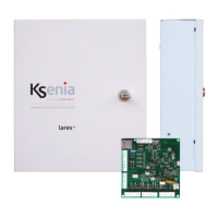
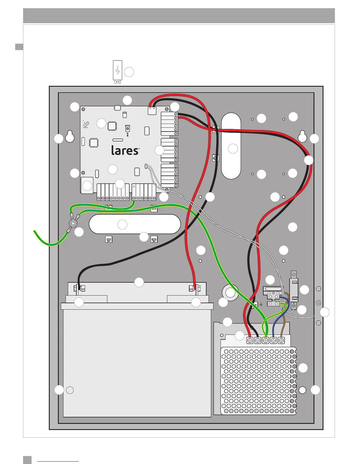
IDENTIFICAZIONE DELLE PARTI
Nella gura seguente, vengono identicate le parti principali che costituiscono il sistema lares. La foto mostra anche
i collegamenti di alimentazione: particolare importanza deve essere attribuita al collegamento della terra. Le due
grandi asole ricavate nel fondo metallico consentono un comodo passaggio cavi per il cablaggio dei dispositivi
periferici anche nel caso di impianti di notevoli dimensioni.
+P1 M1 M2 - +P1 M3 M4 -
NC C NO +A +R
+P i1 i2 - - - - -+P +Pi3 i4 i5 i6 A B+ 12V
CENTRALE - CONTROL PANEL
CENTRALE - ZENTRALE
L
N
1
22
21
20
19
19 19
19
18
17 17
16
15
14
13
2
23
2
2
3 3
3 3
4
4
44
5
5
5
5
6
6
7
8
9
10
11
11
12
 Loading...