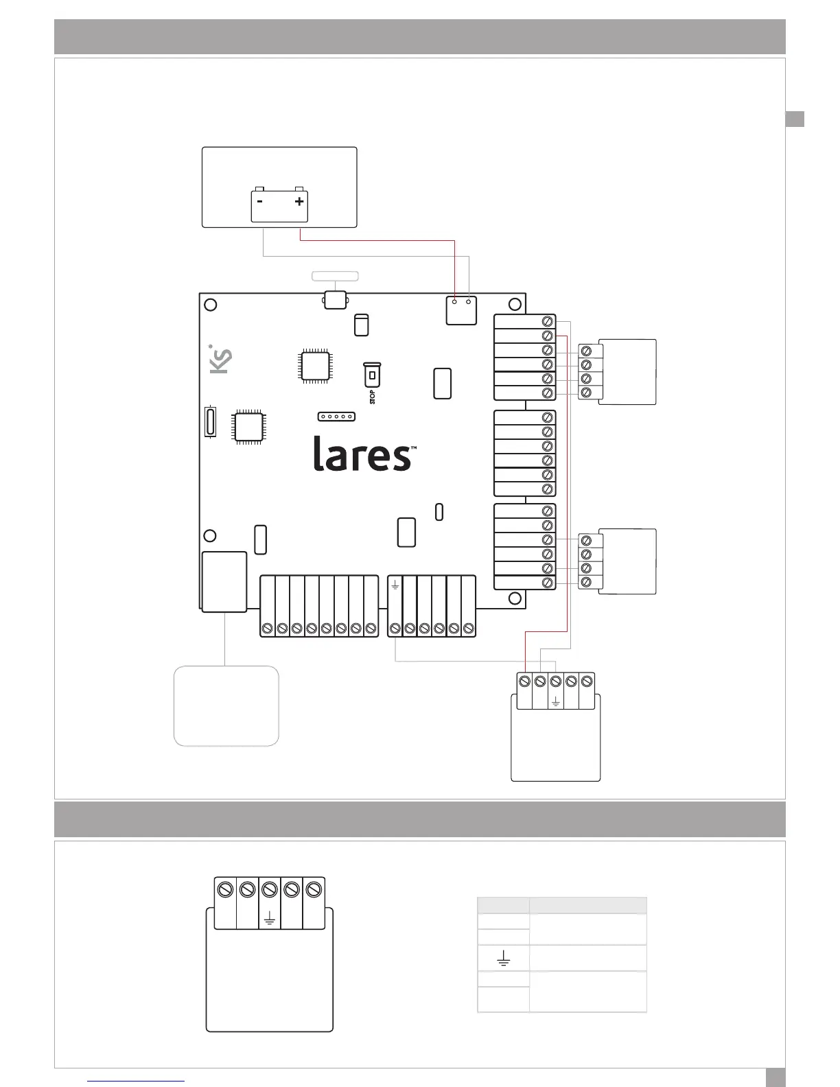
TYPICAL CONNECTION DIAGRAM
A basic connection diagram is shown in gure. To assist the installer, a label on the back of the metal cover of every
lares system reports the necessary connections for correct operation, as shown below:
+V N L-V
POWER SUPPLY
BATTERY
+P1 M1 M2 - +P1 M3 M4 - NC C NO +A +R
+P i1 i2 - - - - -+P +Pi3 i4 i5 i6 A B+ 12V
CENTRALE - CONTROL PANEL
CENTRALE - ZENTRALE
- AB +
KS-BUS
USB PORT
ETHERNET CABLE
lares 16-IP 48-IP 128-IP
DETECTORS
DESCRIPTION OF POWER SUPPLY CONNECTION
+V N L-V
TERMINAL DESCRIPTION
+V
Power output
14,2V
-V
Protection ground
N
Power Supply Voltage
220Vac
L
 Loading...