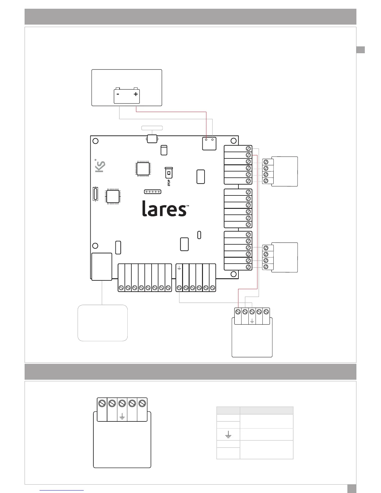
SCHEMA DI COLLEGAMENTO GENERICO
Uno schema base di collegamento è riportato in gura. Per facilitare l’installatore, su ogni centrale lares nel retro del
coperchio metallico è stata apposta un’etichetta con i collegamenti necessari per il corretto funzionamento come
di seguito mostrato.
+V N L-V
ALIMENTAZIONE
BATTERIA
+P1 M1 M2 - +P1 M3 M4 - NC C NO +A +R
+P i1 i2 - - - - -+P +Pi3 i4 i5 i6 A B+ 12V
CENTRALE - CONTROL PANEL
CENTRALE - ZENTRALE
- AB +
KS-BUS
PORTA USB
CAVO ETHERNET
lares 16-IP 48-IP 128-IP
SENSORI
DESCRIZIONE DEI MORSETTI DI COLLEGAMENTO SULL’ALIMENTATORE
+V N L-V
MORSETTO DESCRIZIONE
+V
Alimentazione in uscita
14,2V
-V
Terra di protezione
N
Tensione di alimentazione
220Vac
L
 Loading...