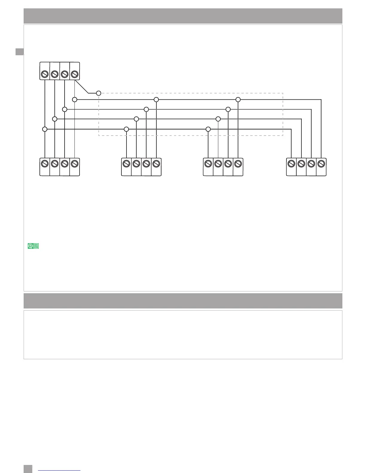
KS-BUS CONNECTION DIAGRAM (RS485)
Peripheral units of the Ksenia system are connected through the fast KS-BUS. It is recommended not to exceed, for
each wiring branch (e.g. control panel - device), the maximum length of 500 m (1400 feet), and the complete wiring
should not be longer than 1000 m (2800 feet). Always use a shielded cable with one end of the shield connected to
the control panel’s ground
6
and the other end free. Figure below is an example.
You should always take care to connect the shield properly, as indicated above, also for connections of other
devices that don’t communicate with the KS-BUS, especially in the presence of very long wiring.
-A B+ -A B+
-A B+
-A B+-A B+
ergo gemino auxi Others BUS
Peripherals
Keypad GSM/GPRS
Communicator
Expansion Module
6 Not the protection ground.
MAINTENANCE
To perform the periodic maintenance of devices please follow the instructions here below:
• Remove the dust eventually deposited on metal cabinet using a damp cloth without any solvent.
• Check the connections and conductors status.
• Check for no external bodies inside of the Control Panel
 Loading...