EasyManuals Logo

KVH Industries TracVision G4 User Manual

KVH Industries TracVision G4
155 pages
To Next Page IconTo Next Page
To Previous Page IconTo Previous Page
Page #106 background imageLoading...
Page #106 background image
Replacing the Main PCB
1. With a PC connected to the ADCU’s maintenance
port, apply power to the antenna unit.
2. Record the system serial number for later re-entry
(the serial number is listed at the beginning of the
startup sequence, as shown in Appendix F on
page 143).
3. Disconnect power from the antenna unit and the
IRD.
4. Remove the PCB cover, as explained in “Removing
the Main PCB Cover” on page 106.
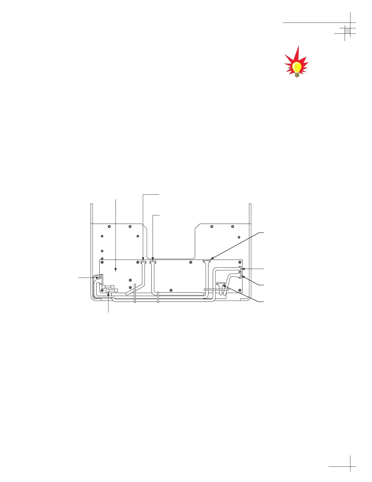
5. Disconnect all Molex connectors from the main PCB
(see Figure 5-3).
Maintenance
54-0147
107
Main PCB
Power/Data
Fuses
Azimuth
Motor
Elevation
Motor
Azimuth/Elevation
Limit Switches
to RF PCB
Antenna Gyro
Cable Wrap
(External Sensor)
Figure 5-3
Main PCB Connector Locations
(Rear View)
Refer to
Section 4.6, “Computer
Diagnostics” on page 98
for
complete details on connecting a
PC to the system via the
maintenance port.

Table of Contents

Questions and Answers:

Question and Answer IconNeed help?

Do you have a question about the KVH Industries TracVision G4 and is the answer not in the manual?

KVH Industries TracVision G4 Specifications

General IconGeneral
BrandKVH Industries
ModelTracVision G4
CategorySatellite TV System
LanguageEnglish

Related product manuals