54-0147
150
TracVision G4 Technical Manual
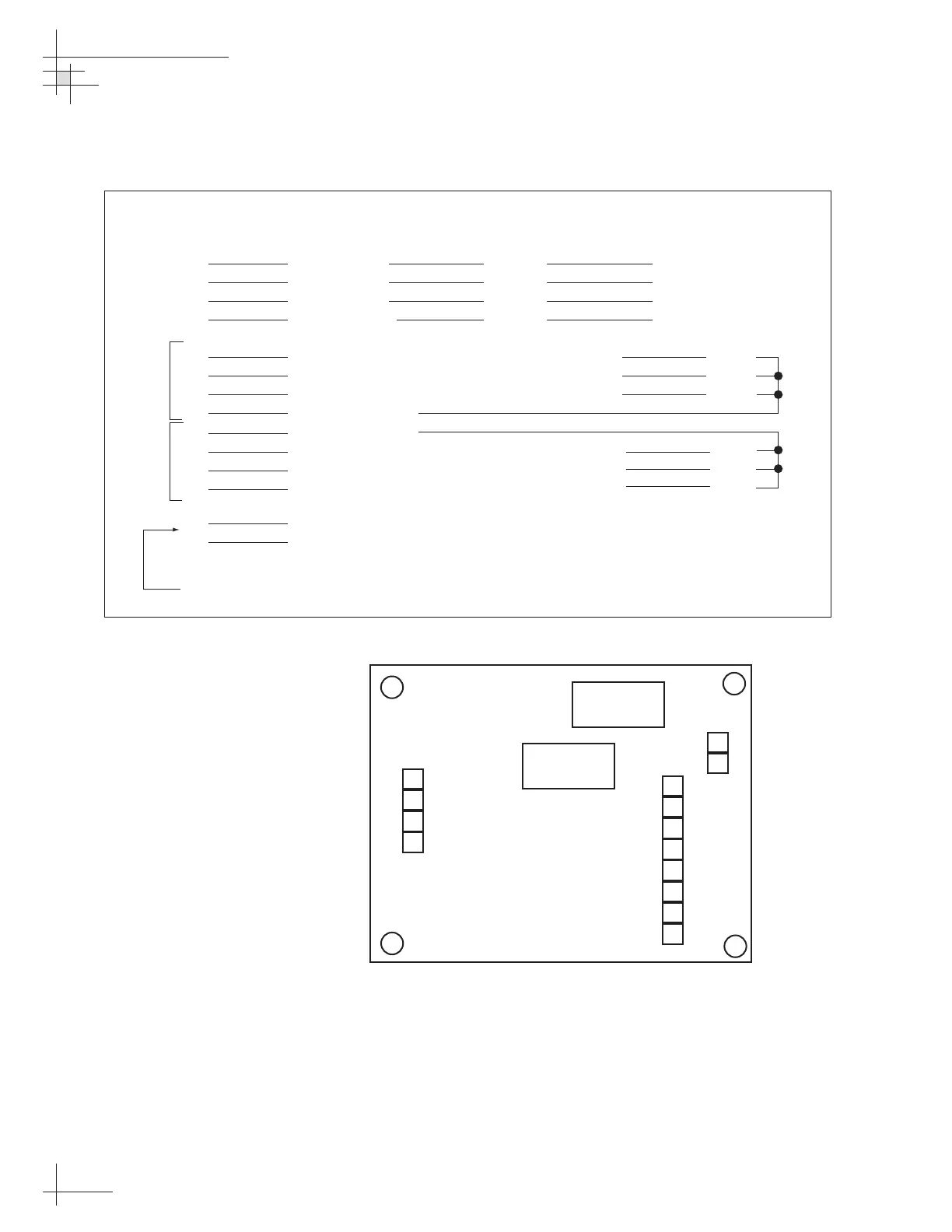
1 Step Line 1 Red 23
2 Step Line 2 Yellow 22
3 Step Line 3 Green 21
4 OV Common Blue 24
5 Step O/P Line 1 -VE Switch Line (Open Drain) Load
6 Step O/P Line 2 -VE Switch Line (Open Drain) Load
7 Step O/P Line 3 -VE Switch Line (Open Drain) Load
8 +VE Supply Out
9 -VE Supply Out
10 Step O/P Line 3 +VE Switch Line (Open Drain) Load
11 Step O/P Line 2 +VE Switch Line (Open Drain) Load
12 Step O/P Line 1 +VE Switch Line (Open Drain) Load
13 Step Supply -VE
14 Step Supply +VE (15-70 VDC)
Interface Box
Terminal
Function Core Color Interface Connector
Terminal Number
6-70 VDC input from converter power supply
negative
logic
positive
logic
The step supply is internally fused at 1 amp. Step output lines are opto-isolated from step input lines.
Fuse 1A
Fuse 1A
14
13
12
11
10
9
8
7
6
5
4
3
2
1
Figure G-2
Optional 6-70 V Stepper Voltage
Converter Wiring Diagram

 Loading...


