2-3/8"
(60mm)
or
2-3/4"
(70mm)
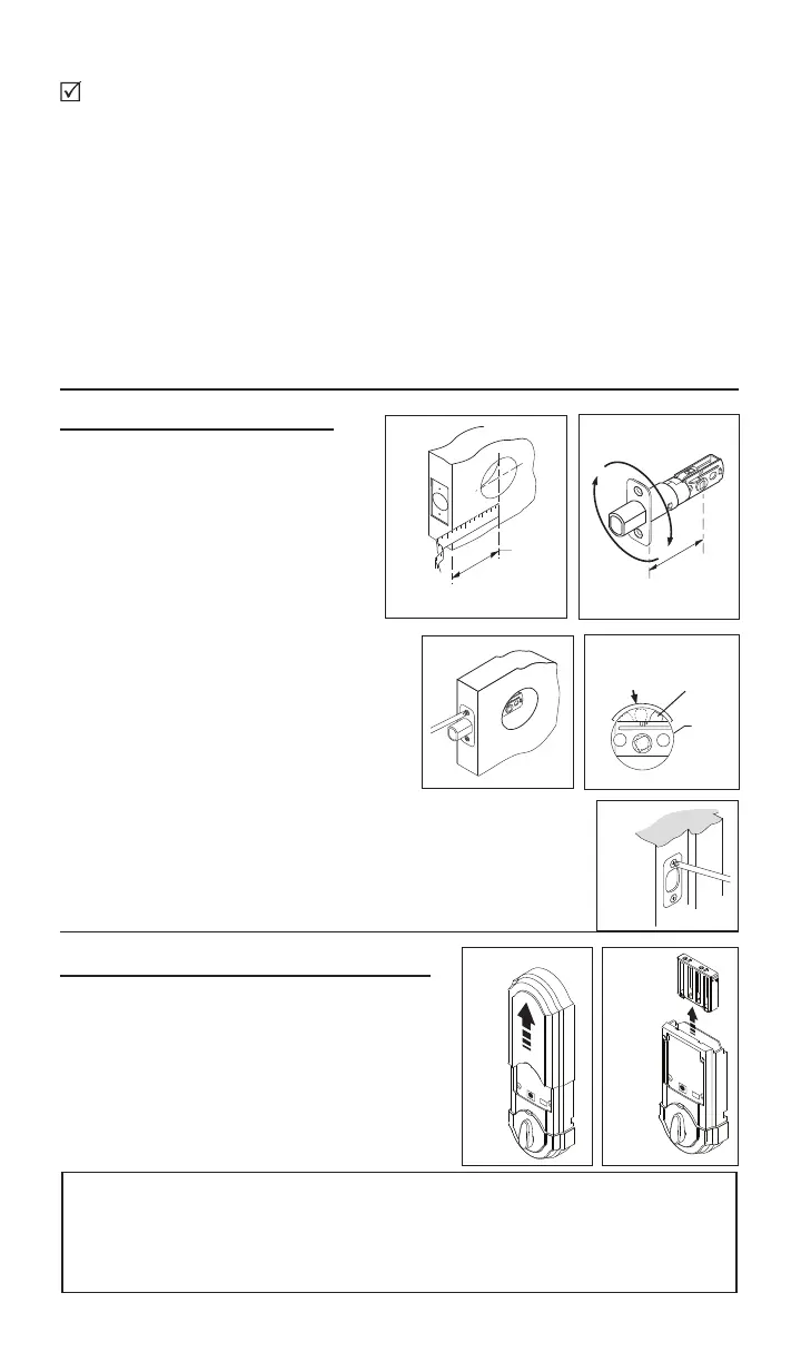
1. Install latch and Strike.
Fig.3
Fig.1
d.Leavetheboltintheextendedposition.
e.Installstrikewithtwo1-1/2”(38mm)woodscrews(see
gure5).
2. Remove cover and battery case.
2
Area
Crank
Use the checklist below to assure completion of important steps.
□PREPAREDOORASREQUIRED............
□INSTALLLATCHANDSTRIKE................
□INSTALLEXTERIORASSEMBLY............
□INSTALLMOUNTINGPLATE...................
□ATTACHCONNECTOR............................
□INSTALLINTERIORASSEMBLY.............
□RUN“BOLTDIRECTION”ROUTINE.......
□PROGRAMCODE(S)................................
□VERIFYOPERATION................................
Ontemplate(included)
Section 1
Section 3
Section 4
Section 5
Section 6
Section 8
Section 9 a, b, c
Section 9 d
a. Determine your backset, see
gure1.
b. Ifa2-3/4”(70mm)backsetis
required, extend bolt and adjust
latch as shown.(Seegure2).
Fig.2
Fig.5
Fig.4
c. Install latch, securing with small
woodscrews(seegure3).Note: For
a 1-1/2” (38mm) diameter hole, test if
latch extends and retracts smoothly.
Area indicated may require addition
clearance for crank of latch to function
properly (see gure 4).
a.
Removecoverfromassemblybysliding
coverupandoff,seegure.6
b.Removethebatterycasefrominterior
assemblybyliftingthecaseupandoutand
setaside,seegure7.
Fig.7Fig.6
Importantbeforeproceeding: 1. Verifythatposition#2ofthe“Settings
Switch”isintheOFFposition.(Refertosection11.)2. Work with the
dooropen(awayfromjamb)toavoidaccidentallockout.3. Make sure
theboltoflatchisintheextended(locked)position.