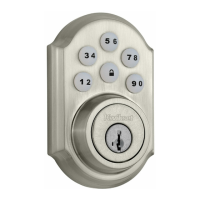
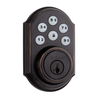
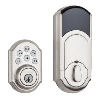
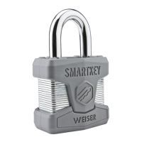
3. Install Exterior Assembly.
Bolt
3
Wire
Harness
Adapter
For2-1/8”
diameteronly.
Fig.9
Fig.8Fig.7
a. Place adapter on door as shown,
(note,adapterisnotrequiredif
mountingona1-1/2”(38mm)
diameterhole.
Crank
Torque
Blade
c. Place assembly on door, threading
thewireharness(throughadapter-if
used)andunderthelatch.
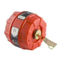
b. Insert cylinder into exterior
assembly.Withkeyincylinder,
rotate the torque blade to align
withcrankinlatch.
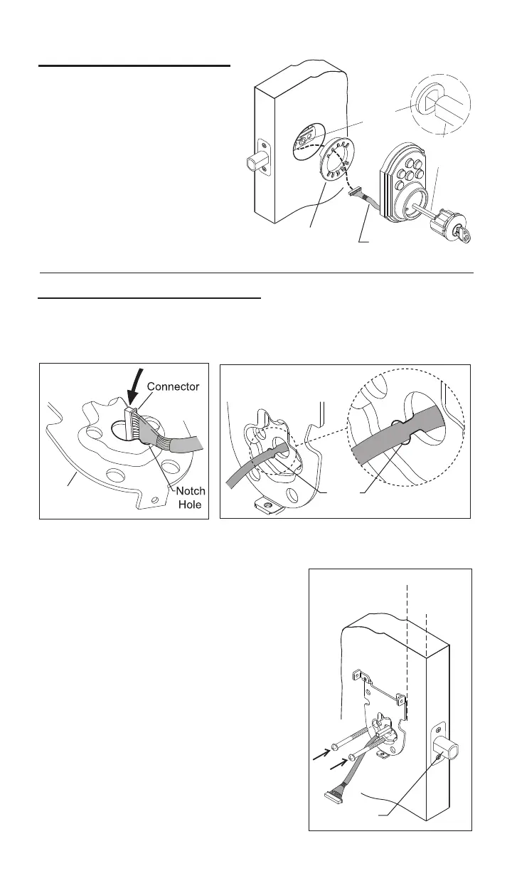
a. Carefullyangletheconnectorofthewireharness-throughthecenter
holeofthemountingplate,utilizingthenotchholetoallowconnectortopass
through(seegure7).
e.Checktheverticalalignmentformounting
plate and exteriorassembly.(Seegure9.)
h.Repeatasrequired.
f.Test.Usingthekey,retractandextendthe
boltafewtimestotestforsmoothaction.
c. Slide wires through the notch until mounting
platesitsushagainstdoor.
4.InstallInteriorMountingplate.
Mounting
Plate
b. Important, once the connector has passed through the center hole, tuck
thewireharnessoutofthewaybypressingitintothenotchholeasshown
ingure8.
Notch
Hole
d. Making sure that exterior assembly and
cylinder arepressedushagainstexterior
door,insertmountingboltsandtighten.
g.Ifactionfeelsrough,loosenscrewsand
re-align the mounting plate and the exterior
assembly.Note:Alsoseestep1-cforpossible
crankinterference.