6. CYLINDER HEAD/VALVES
SERVICE INFORMATION
GENERAL INSTRUCTIONS
• The cylinder head can be serviced with the engine installed in the frame.
• When assembling, apply molybdenum disulfide grease or engine oil to the valve guide movable
parts, valve arm and camshaft sliding surfaces for initial lubrication.
• The valve rocker arm is lubricated with engine oil through the cylinder head engine oil passages.
Clean and unclog the oil passages before cylinder head assembly.
• After disassembly, clean the removed parts and dry them with compressed air before inspection.
• After removal, mark and arrange the removed parts in order. When assembling, install them in
the reverse order of removal.
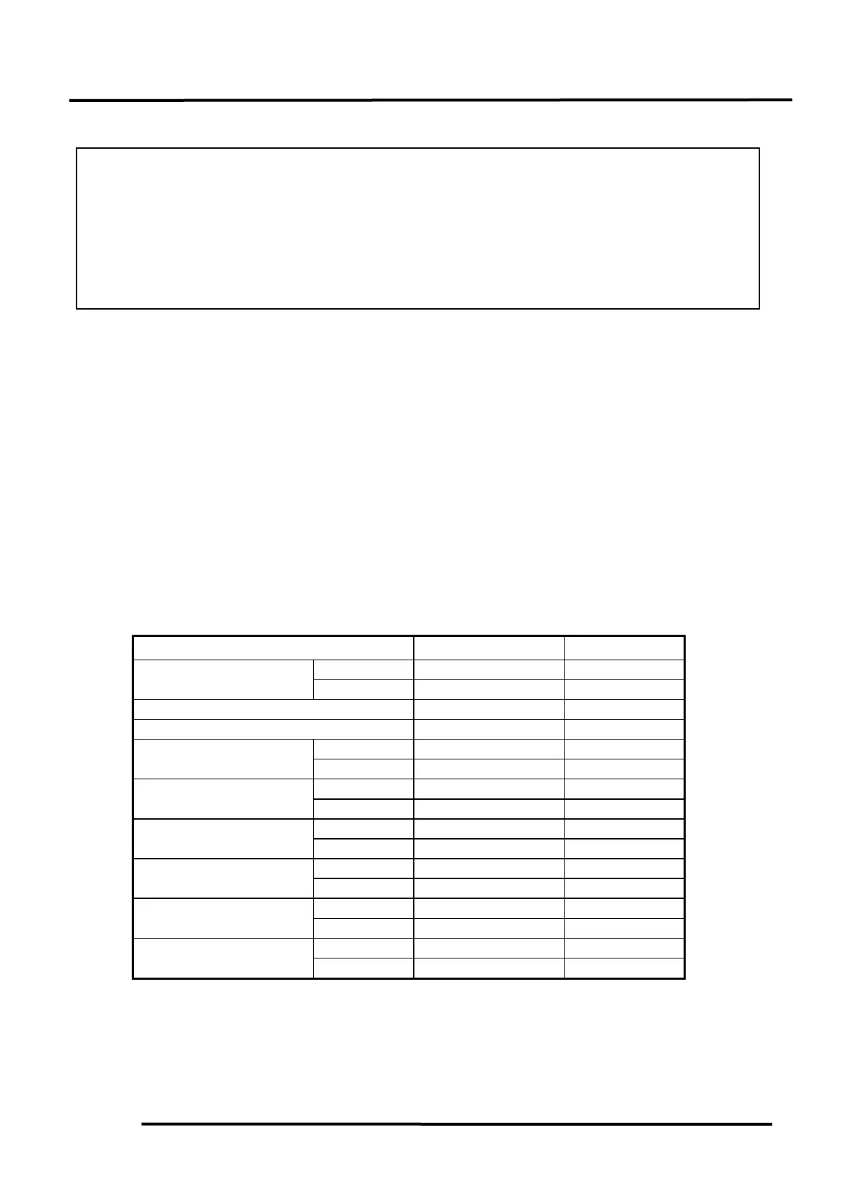
SPECIFICATIONS
Item Standard (mm) Service Limit
IN 0.05~0.11
Valve clearance (cold)
EX 0.05~0.11
Cylinder compression pressure kg/cm² 10~14 8
Cylinder head warpage 0.05 0.1
IN 0.10~0.025 0.4
Rocker arm clearance
EX 0.10~0.025 0.4
IN 0.013~0.046 0.126
Rocker arm-to-shaft
clearance
EX 0.013~0.046 0.126
IN 89°~90° 90°
Valve seat angle
EX 89°~90° 90°
IN 5.30~5.40 5.27
Valve stem O.D.
EX 5.30~5.40 5.27
IN 5.475~5.485 5.485
Valve guide I.D.
EX 5.475~5.485 5.485
IN 0.01~0.035 0.035
Valve stem-to-guide
clearance EX 0.03~0.055 0.055
SERVICE INFORMATION......................6-1 VALVE GUIDE REPLACEMENT...........6- 6
TROUBLESHOOTING............................. 6-3 VALVE SEAT INSPECTION & REFACING ....6- 7
ROCKER ARM SET REMOVAL............6-4 CYLINDER HEAD ASSEMBLY .............6- 9
CYLINDER HEAD REMOVAL ..............6-4 CYLINDER HEAD INSTALLATION......6-10
CYLINDER HEAD DISASSEMBLY ......6-5