11. FRONT WHEEL/SUSPENSION/
STEERING
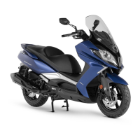
Remove the two handlebar lock nuts to
remove the handlebar.
INSTALLATION
Install the handlebar in the reverse order of
removal.
Torque: 0.8~1.2kg-m
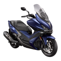
When installing the right and left handlebar
switch housings, align the pin on the housing
with the hole in the handlebar. Tighten the
two switch housing screws.
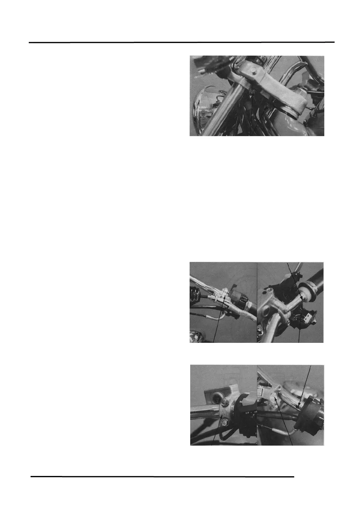
When installing the master cylinder and
clutch lever holders, align the tab on the
holder with the hole in the handlebar with
the holder “UP” mark facing up.
First tighten the upper bolt and then the
lower bolt.
Torque: 1.0~1.4kg-m
 Loading...