2GN/2GP/2GR-6
1-2-12
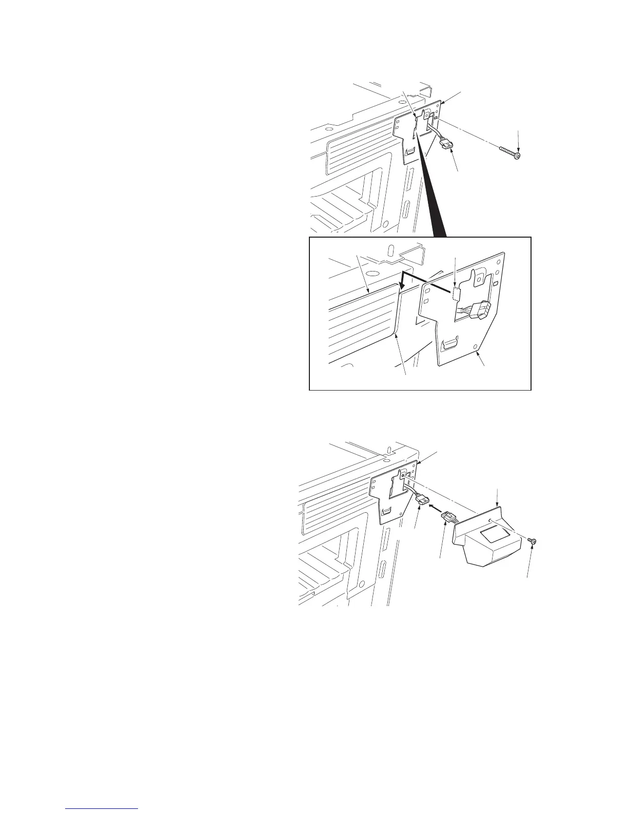
7. Pass the connector of the machine through
the aperture in the key counter cover
retainer.
8. Insert the hook of the key counter cover
retainer in the slit of the upper right cover.
9. Fit the key counter cover retainer to the
machine using the M4 x 20 screw.
10. Refit the scanner right cover.
Figure 1-2-18
11. Insert the connector of the key counter sig-
nal cable into the connector of the machine.
12. Fit the key counter cover with the key
counter socket assembly inserted to the key
counter cover retainer using the M4 X 6
screw.
13. Insert the key counter into the key counter
socket assembly.
Figure 1-2-19
14. Turn the main power switch on and enter the
maintenance mode.
15. Run maintenance item U204 and select ON.
16. Exit the maintenance mode.
17. Check that the message requesting the key
counter to be inserted is displayed on the
touch panel when the key counter is pulled
out.
18. Check that the counter counts up as prints
are made.
Connector
Hook
Upper right cover
Slit
Key counter
cover retainer
Key counter
cover retainer
Aperture
M4 x 20 screw
(7BB100420H)
M4 x 6 screw
(B4A04060)
Key counter
signal cable
Connector
Key conuter cover
Key counter
cover retainer

 Loading...