―
13
―
(andtheprospectivefaultcurrenthighenough)toallowautomatic
disconnectionoftheelectricalsupplybythecircuitprotectiondevicewithina
prescribedtimeinterval.
Everycircuitmustbetestedtoensurethattheearthfaultloopimpedance
valuedoesnotexceedthatspecified or appropriate for theover-current
protectivedeviceinstalledinthecircuit.
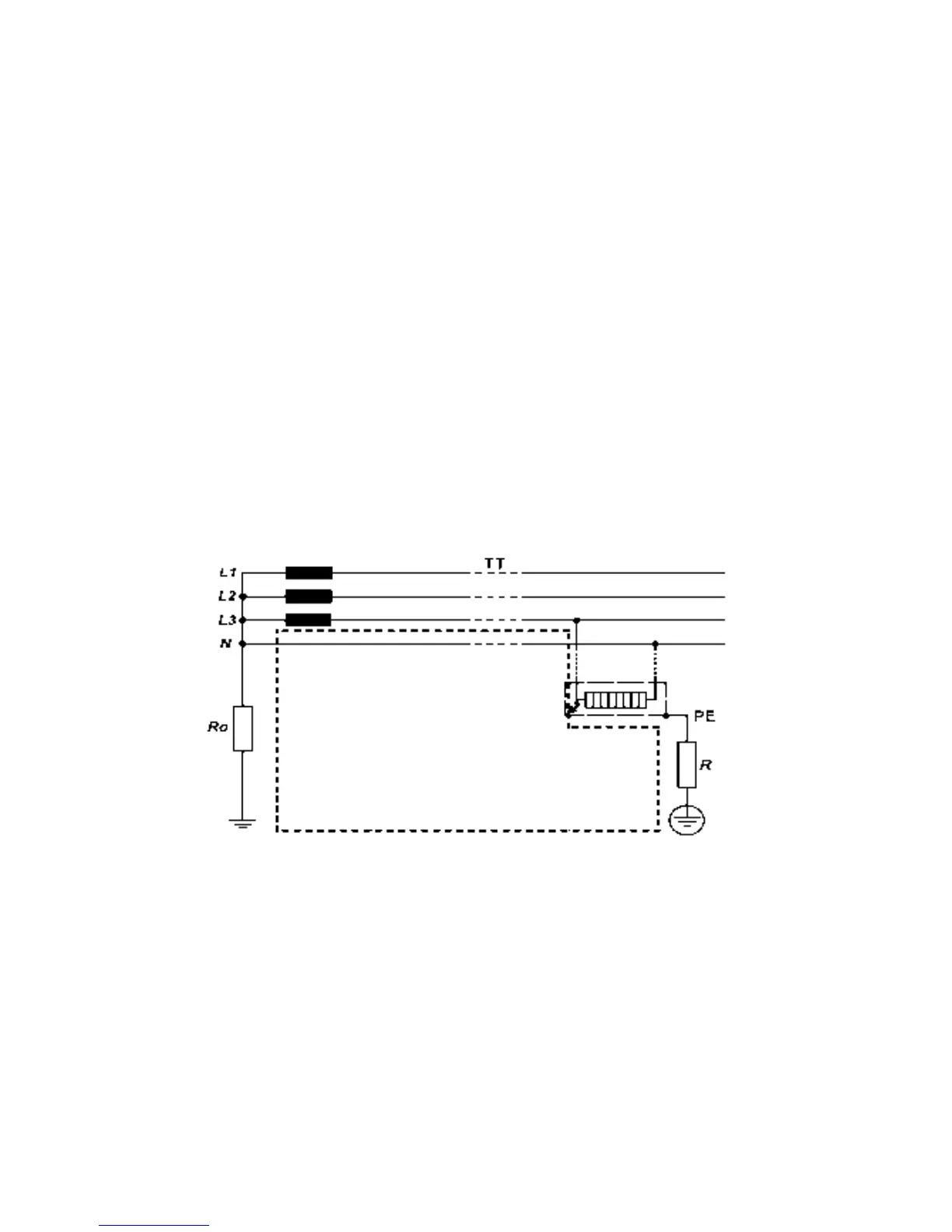
ForaTTsystemtheearthfaultloopimpedanceisthesumofthefollowing
impedances;
● Impedanceofthepowertransformersecondarywinding.
● Impedanceofthephaseconductorresistancefromthepowertransformer
tothelocationofthefault.
● Theimpedanceoftheprotectiveconductorfromthefaultlocationtothe
localearthsystem.
● Resistanceofthelocalearthsystem(R).
● Resistanceofthepowertransformerearthsystem(Ro).
ForTNsystemstheearthfaultloopimpedanceisthesumofthefollowing
impedances.
● Impedanceofthepowertransformersecondarywinding.
● Impedanceofthephaseconductorfromthepower transformer tothe
locationofthefault.
● Impedanceoftheprotectiveconductorfromthefaultlocationtothepower
transformer.
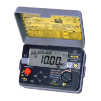
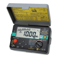
Fig.9