―
17
―
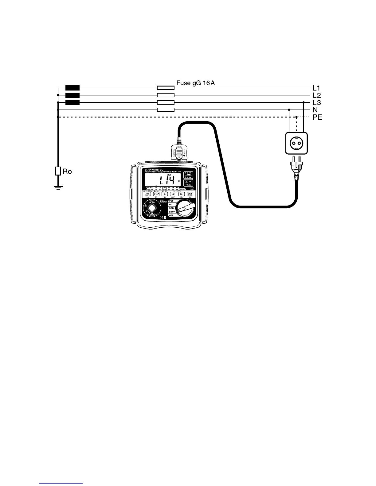
PracticalexampleofverificationoftheprotectionisaTTsystem
accordingtotheinternationalStandardIEC60364.
Fig.12
ThemaximumvalueofZsforthisexampleis2.1Ω(16ampgGfuse,0.4
seconds).The loop tester reads 1.14Ωand consequently the condition
Zs
<
Uo/laismet.
5.1.2PrinciplesoftheMeasurementofLineImpedanceand
ProspectiveShortCircuitCurrent
Lineimpedanceistheimpedance,whichismeasuredbetweenPhase-
terminalLandNeutral-terminal N of single-phasesystem,orbetween
twophasesofthree-phasesystem.Measurementprincipalusedinthis
instrumentisthesameasitforFaultloopimpedancemeasurement,but
measurementisperformedbetweenTerminalLandN,orbetweentwo
phases.
Breakingcurrentcapacityof installed over-current protectiondevices
shouldbehigherthanProspectiveShort-Circuitcurrent,otherwiseitis
necessarytochangetheratedcurrentofinvolvedover-current
protectiondevice.