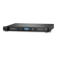
The values for VPL are displayed as maximum Voltage
Peak. To translate Voltage Peak into Vrms, you must
divide the Voltage Peak values by 1.41 (see table).
The VPL allows you to set the correct maximum
output peak power for optimum performance with
the connected speakers. The correct setting depends
on the system type and the specific load connected
to the channel. Since each channel can be configured
to deliver either very high voltage peak power OR
high current draw at low-impedances, it is important
to set the VPL correctly.
If you choose a lower VPL setting, you only reduce
the maximum output voltage. At the same time, this
allows more current headroom for low-impedance
loads. The amplifier thus runs at higher efficiency,
with a significantly reduced risk of going into thermal
protection.
7.4.8 Output Current Peak Limiter (CPL)
The Current Peak Limiter (CPL) ensures that the
amplifier will not be damaged by forcing the amplifier
to deliver current levels to the outputs that exceed
the physical limits of the transistors. The CPL keeps
the amplifier within the Safe Operating Area.
The CPL is non-adjustable and has different limit
values depending on model type.
CPL activity is indicated by illumination of an orange
LED for each channel on the front-panel. Warnings
also are shown in the DeviceControl software’s
GUI.
A steadily illuminated orange CPL LED (with MUTE
illuminated) indicates a short circuit situation (or very
low-impedance). The output will mute for 6 seconds
before measuring the output impedance again. This
will continue until the short circuit is fixed, at which
time the output will automatically un-mute. An input
signal must be present to allow detection of short
circuit or low-impedance conditions.
The problem can be solved by checking
input and output cables and examining the
state of the loudspeaker load. If there is no
short circuit present, then the condition may
be rectified by lowering the VPL or input levels.
7 OPERATION AND PERFORMANCE

 Loading...