6 QUICK GUIDE OVERVIEW
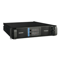
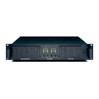
The amplifier’s front-panel presents the performance
and fault condition indicators, power and remote
switches, and a removable dust-filter cover. Level
potentiometers provide individual attenuation for the
amplifier channels. Range is 0 dB to - infinity. (The
12 o’clock position indicates -10 dB attenuation.) A
convenient label strip with writing surface is provided
adjacent to each level potentiometer.
To remove the dust-filter covers, loosen the thumb-
screws located underneath the front handles. This
allows removal of the dust-filters for cleaning. The
covers may be made “tamper resistant” by replacing
the thumbscrews with Philips head or safety Torx
screw. Thread size is M3.
The amplifier never should be operated
without the dust-filters in place.
6.1.1 Power on/off and remote switch
The Power on/off switch is located on the right side.
A second switch, labeled “REMOTE,” is above the
Power switch. When the Remote switch is on (with
mains connected and power on/off switch on), the
yellow LED above it will illuminate indicating that
external power on /of f commands from the Nomad Link
network connection will switch the amplifier on or
off. When Remote is activated the amplifier will not
switch on until a “Power On” command is received
from the network. When the remote switch is off,
it is not possible to switch amplifier power on or off
using NomadLink network control.
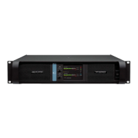
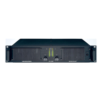
6.1.2 Front-panel LED’s
The front-panel LED area includes the following
indicators per channel:
.
6.1 Front-Panel overview
VHF
•
- Ver y High Frequency protection active (output muted)
(Yellow constant)
TEM• - Temperature warning (Yellow flashing)
TEM• - Temperature mute (Yellow constant)
MUTE• - Channel muted via NomadLink network or due
to a fault condition (Red)
CPL• - Current Peak Limiter (CPL) active (Orange flashing)
CPL• - (Orange constant with output muted): Low impe-
dance / short circuit detection fault
VPL• - Voltage Peak Limiter (VPL) active
SIG• - Signal levels - 40 dB (Sig) to –4 dB
Hi-Imp• - High-impedance/open load detected (Orange)
Bridge• - Bridge mode operation (Yellow)
.
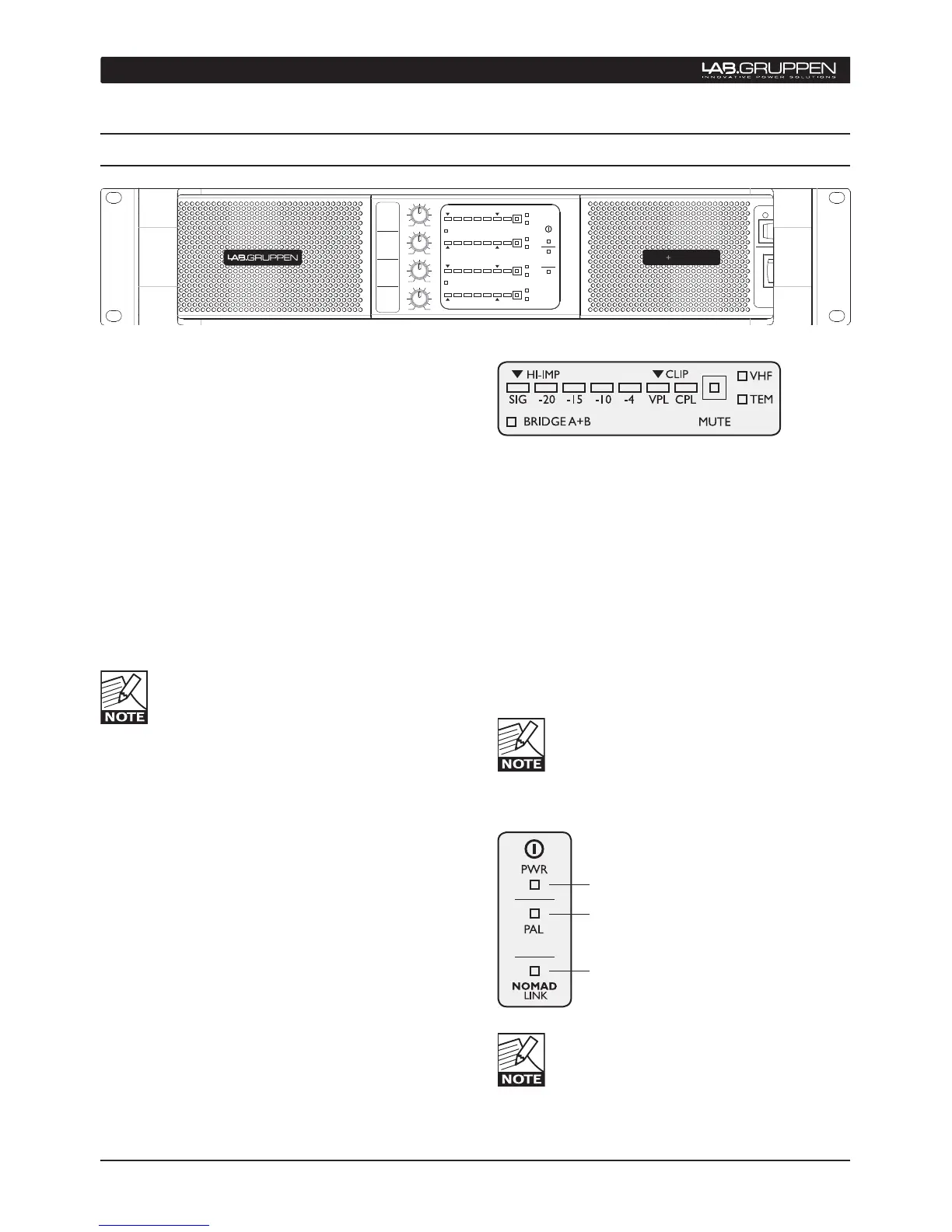
(PWR) Power on (Green)
(PAL) Power Average Limiter active (Red)
NomadLink network active (Blue)
When no VPL, CPL or PAL indicators are illumi-
nated, and the VPL DIP switch is set to maximum
at the specified nominal load, the amplifier
channel is able to deliver maximum rated output
power
When the network is connected, the blue
NomadLink LED will illuminate even when
mains power is not connected. NomadLink
receives phantom power from the network as
supplied by the NLB 60E.

 Loading...