7.6 Front-panel monitoring and
adjustments
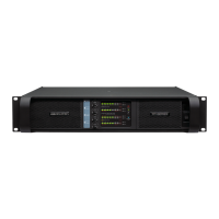
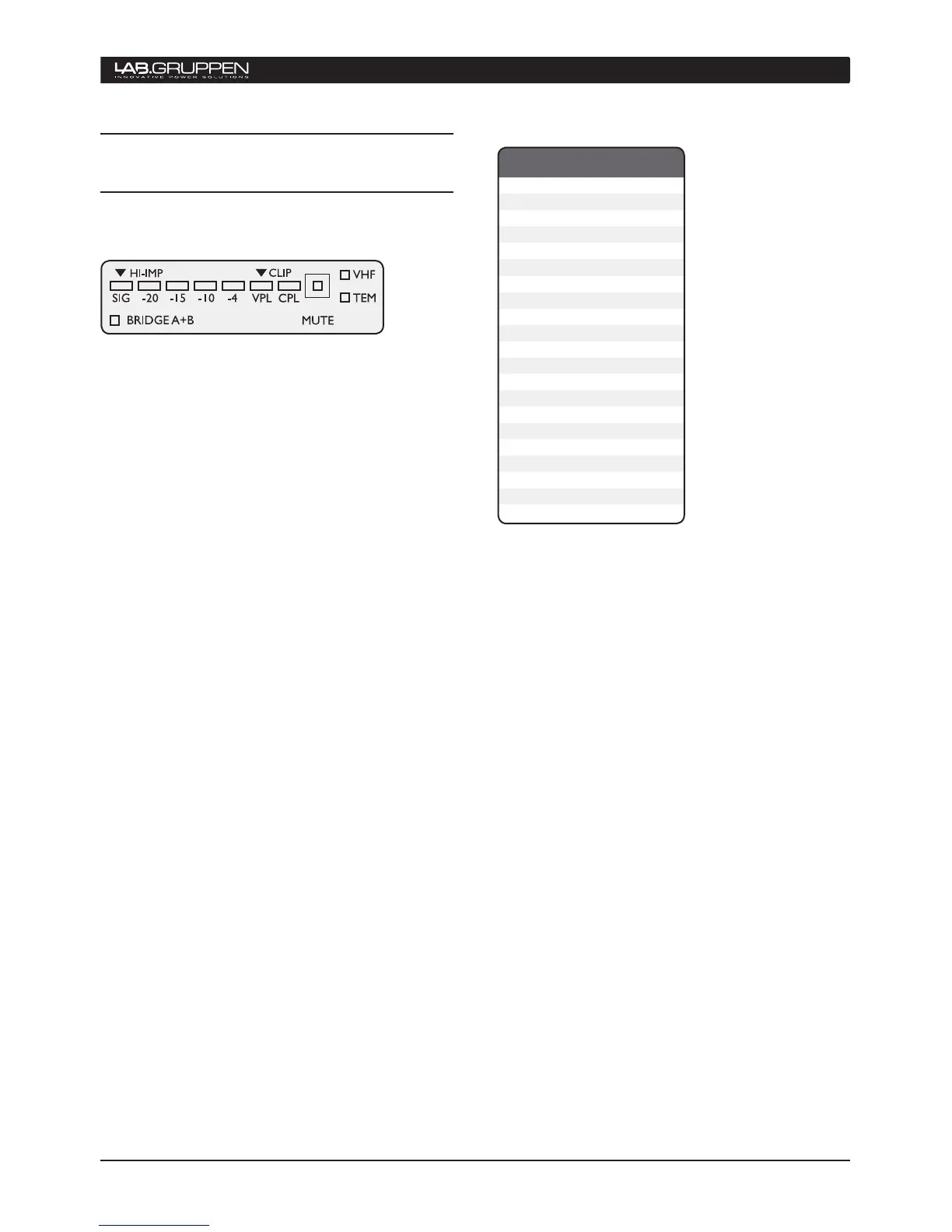
7.6.1 Level indicators
The front-panel displays an array of ten LED indica-
tors for level and status monitoring of each amplifier
channel. Indications related to signal levels are as
follows:
Orange CPL (Current Peak Limiter)
•
flashing
Indicates that output signal has reached the limit
of the output devices and limiting is in effect.
Red VPL/CLIP
•
Indicates that signal has reached
maximum output voltage. (Maximum voltage is
determined by rear-panel VPL settings.)
Green SIG to -4• Indicates output signal levels
in normal operating range
SIG + HI-IMP (green/orange)• Indicates input
signal above –44 dB. Should the SIG indicator
turn red, this indicates a “high-impedance”
or open connection has been detected at the
output. Possible faults include a disconnected
cable or malfunctioning loudspeaker. (In some
cases a normal condition, such as a sub-bass
enclosure with high-impedance at a certain
frequency, can trigger this indication.) If the -10
dB LED illuminates AND the HI-IMP LED turns
orange, then the amplifier has detected an open
load (no loudspeaker connected).
More detailed signal indications are available using
the DeviceControl software application.
7.6.2 Level adjust
Level adjust potentiometers (one per channel) are
located on the front-panel adjacent to the LED display.
The potentiometer’s operational range is 0 dB to
minus infinity in 21 steps. Attenuation is logarithmic,
with -10 dB at the 12 o’clock position. See table for
levels at other increments.
OPERATION AND PERFORMANCE 7
Note that it is not possible to adjust individual chan-
nel attenuation from the NomadLink network or
elsewhere on the amplifier.
7.6.3 Mute indication
Individual channel Mute is indicated by illumination of
the red MUTE LED provided for each channel. If only
the red MUTE LED is illuminated and all other indica-
tions are normal, then the channel has been muted
by a command from the NLB 60E bridge front-panel
or the DeviceControl application. Otherwise, an
illuminated MUTE LED could indicate a fault condition
(see below).

 Loading...