6.5 Gain Settings
The architecture of the PLM Series provides gain
adjustments at a number of points in the signal flow
path. Thus, there are many places in which one can
adjust the levels in the PLM. Each point serves a
different purpose.
More detailed information on gain settings can be
found in the PLM Operation Manual section 8.1.
The following can be used as guidelines for adjust-
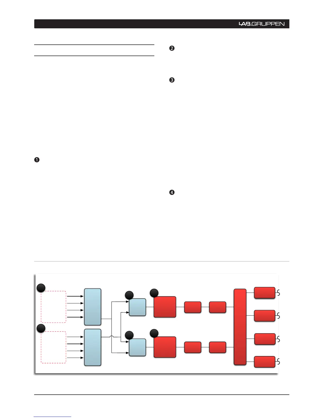
ment of the gain settings, from input to output. The
block signal flow diagram below can also be used as
a reference to help in understanding the signal path
through the PLM’s architecture:
Input headroom (Analog Inputs)
As a rule, this should be set to 12 dBu if the source
is (or can be) limited to 12 dBu; otherwise it should
be at 26 dBu. This setting has no direct influence
on the rest of the gain stages in the PLM, or on the
overall noise floor. The PLM’s variable input gain is
strictly meant to provide the appropriate headroom at
the input stage. (Adjust in I/O Config window, Input
Configuration, left side.)
Input mixer
This setting should be left at “0” for most setups. If
only one input channel is used, the other can be set
to “- inf”. (Adjust in I/O Config, module pane.)
Module output gain (Levels)
Two points of gain level adjustments are provided per
Module output. They are used to balance the mutual
gain between frequency bands in a multi-way set up,
and can be described as follows:
- Manufacturer gain: This is “hidden” within the
module file and is set by the creator of the file. As
such, it is not user editable.
- User gain: This is editable by a user. The module file
(part of the fingerprint) contains a default value for this
as well as the manufacturer gain. If the manufacturer
gain is set to a non-zero value, then the default user
gain is zero dB so that the user can easily see any
changes that have been made to this setting. It should
normally not need to be adjusted by the user.
Output gain (Levels)
One adjustment is provided per output channel in
the module to balance the mutual gain between
frequency bands in a multi-way set up. Generally, this
6 QUICK START TUTORIAL
Figure 6.5: PLM Signal Flow Diagram (Part 1)
 Loading...