TRIP COMPUTER CONTROL
(in the design variant)
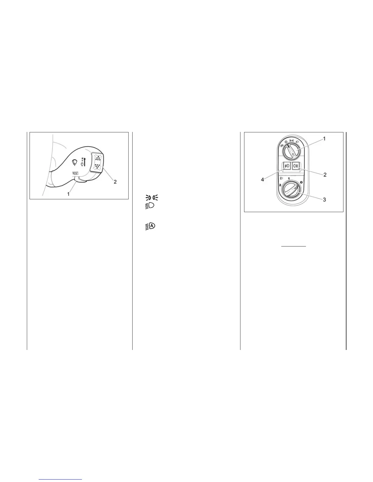
Trip computer control buttons are
shown in Figure 31:
Button 1 – reset of trip computer
readings, gear change prompt tone
switch on/off.
Button 2 (when pressing the
key upper arrow) – switching the
selection mode of the trip computer
functions «in a loop» forward, setting
minutes in the time setting mode.
Button 2 (when pressing the
key lower arrow) – switching the
selection mode of the trip computer
functions «in a loop» backward, set-
ting hours in the time setting mode.
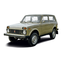
LIGHTING CONTROL
MODULE AND DIPPED
BEAM ADJUSTER
Exterior light switch 1 (Fig. 32a)
has three fixed positions (or four in
the design variant):
О – exterior lights are switched
off;
– tail lights are switched on;
– dipped or main beam is
switched on depending on the posi-
tion of the light alarm switch;
– in the design variant in
this position the tail lights or the
dipped beam headlight is switched
on/off automatically depending on
the exterior lighting. The light sensor
is combined with the rain sensor and
is located on the windshield behind
the rear-view mirror.
The exterior lighting automatic
control system (lighting system)
allows to switch on and off the tail
lights and the dipped beam head-
lights depending on the level of exte-
rior lighting. For example, in twilight,
as well as at the entrance to the tun-
nel or the garage.
The lighting system operates only
when the ignition is on.
Warning
The moment of switching on the
exterior lighting by automatic
control system may not meet the
safety requirements. Therefore,
use of this system does not relieve
the driver of responsibility for
observing safety requirements
and traffic rules.
Dipped beam adjuster switch.
Before operation of the vehicle with
dipped beam headlights switched
on, make sure of the correct position
of the dipped beam hydraulic
adjuster handle 3 depending on the
vehicle load state.
44
Fig. 31. Trip computer control
buttons on the wiper lever
(in the design variant)
Fig. 32a. Lighting engineering
control module and dipped beam
adjuster