just under it. To facilitate the jack cor-
rect installation location, special holes
for the lifting jack are provided on the
vehicle sills. By rotating the jack han-
dle (position I) lift the wheel above the
support surface to a height of 50-60
mm. If the distance to the support
surface does not provide a complete
turn of the handle, then rotate the
handle with small radius (position II);
– unscrew the bolts and remove
the wheel. Mount the spare wheel,
turn in the bolts and tighten them
evenly crosswise;
– lower the vehicle and remove
the jack. Tighten the bolts and check
the tire pressure.
When finished, lay the replaced
wheel in the luggage compartment
bay, secure it with screw 1 (Fig. 55)
and cover with the mat.
After the vehicle first 1000 km run
it is necessary to check the torque-
turn wheel bolt tightening, tighten if
required. Perform the same opera-
tion during every new wheel installa-
tion on the vehicle.
In the design variant the built-up
steel spare wheel is used on the vehi-
cles alloy wheels.
87
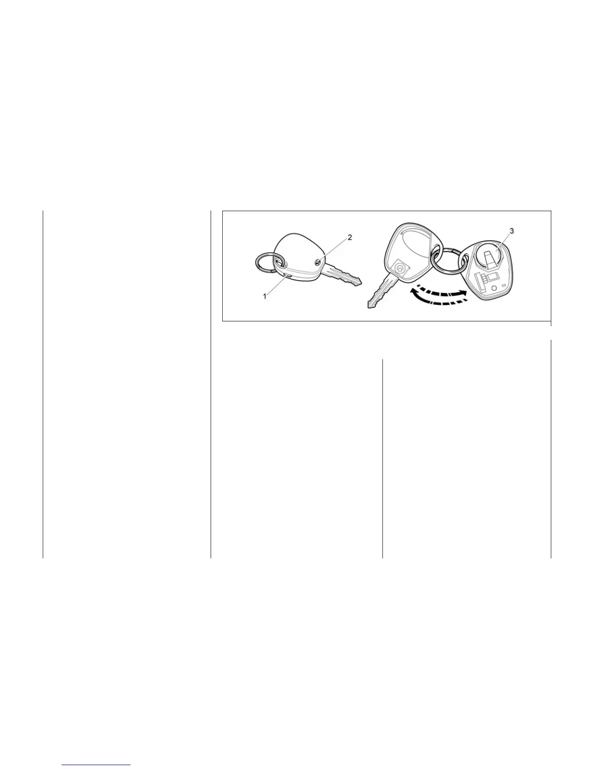
Fig. 56. The remote control battery replacement
REMOTE CONTROL BATTERY
REPLACEMENT
The remote control contains a
lithium battery of CR2032 type with
the initial voltage of 3 V. If the voltage
of the remote control is normal, then
every time you press any button on
the remote control panel its indicator
will light with short flash. If at press-
ing any button of the control panel
the indicator lights with two short
flashes or does not light at all, the
battery should be replaced with a
new one. To do this, perform the fol-
lowing operations:
– open cover (Fig. 56) on the con-
trol panel, shifting it in the arrow
direction;
– remove the battery sealer;
– replace the battery 3 with the
new one observing the polarity;
– close the battery sealer 2;
– slide the cover 1 in on the con-
trol panel case.