8.10 Rear Panel Connector Definition 139
| www.lakeshore.com
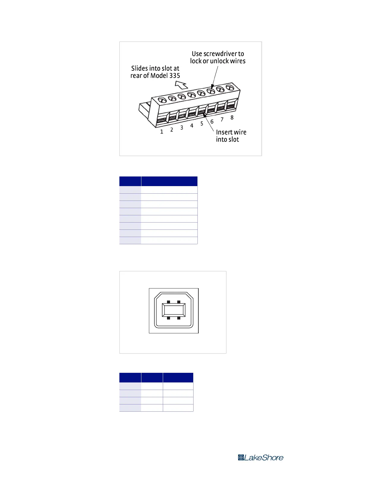
FIGURE 8-5 Terminal block for relays and Output 2 voltage
Pin Description
1 Output 2+
2 Output 2–
3 Relay 1 normally closed
4 Relay 1 common
5 Relay 1 normally open
6 Relay 2 normally closed
7 Relay 2 common
8 Relay 2 normally open
TABLE 8-4 Terminal block pin and
connector details
FIGURE 8-6 USB pin and connector details
Pin Name Description
1 VCC +5 VDC
2 D- Data –
3 D+ Data +
4 GND Ground
TABLE 8-5 USB pin and connector
details