3 .7 .5 P ow eri ng O utp ut 2 Us i ng an E xte r na l P o we r S up ply 39
| www.lakeshore.com
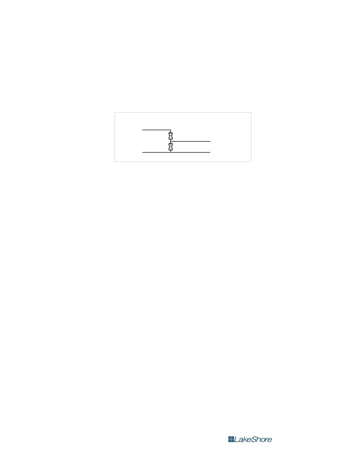
3.7.5.4 Programming Voltages Under 10 V
A voltage divider (FIGURE 3-10) can be used to reduce the control output voltage if
the programming input of the power supply has a range of less than 0 V to 10 V to
ensure full output resolution, and protection against overloading the external supply
programming inputs. The output voltage is proportional to the ratio of resistors
R1 to R2: V
out
= 10 V × R1/(R1+R2). It is also important to keep the sum of
R1
+ R2 > 1000 ) or the Model 335 output may not reach the output voltage setting
due to internal overload protection. For a programming input range of 0 V to5 V, rec
-
ommended values are: R1 = R2 = 2000 ). For a programming input range of 0 V to1 V,
recommended values are: R1 = 500 ), R2 = 4500 ). Exact resistor value, type and tol
-
erance are generally not important for this application.
FIGURE 3-10 Voltage divider circuit for Output 2 (voltage mode)
Model 335
Output 2 +
(voltage mode)
Output 2–
(voltage mode)
Power supply
Program input+
Program input–
R2
R1
 Loading...


