138 cHAPTER 8: Service
Model 335 Temperature Controller
8.10 Rear Panel
Connector
Definition
The sensor input, heater output, terminal block, USB, and IEEE-488 connectors are
defined in
FIGURE 8-3 through FIGURE 8-7. For thermocouple connector details refer
to FIGURE 3-7.
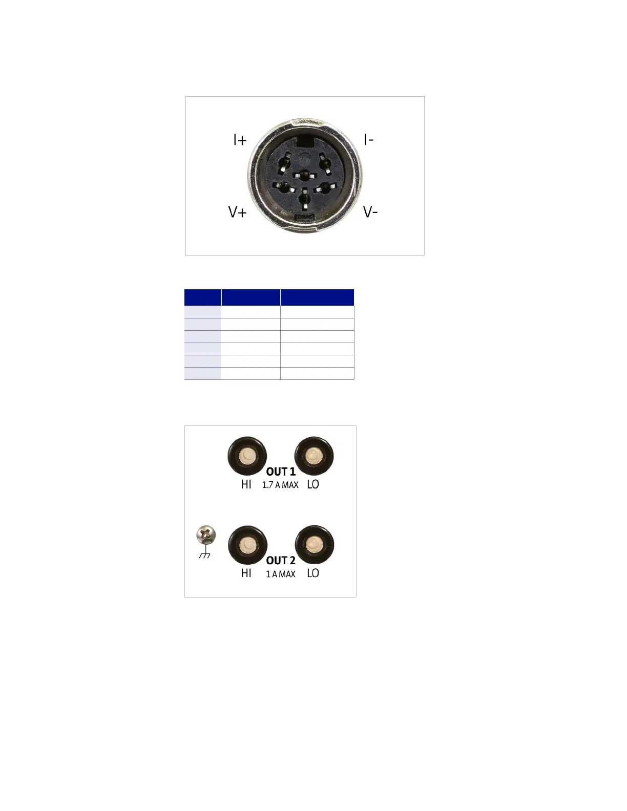
FIGURE 8-3 Sensor input A and B
Pin Symbol Description
1 I– –Current
2 V– –Voltage
3 None Shield
4 V+ +Voltage
5 I+ +Current
6 None Shield
TABLE 8-3 Sensor input A and B
connector details
FIGURE 8-4 Heater output connectors