19
4 Design and Functions
4 Design and Functions
4.1 Design
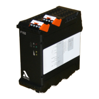
The flame monitor consists of the flame monitoring system F152 and the flame scanner
FFS07 or FFS08.
Connection:
The connection is made via plug-in screw terminals at the F152.
Terminals used for:
• Feed in axillary power (mains)
• Flame signal/indicator signal
• Measuring power for intensity
• Flame sensor cable
Alignment of the control and operating elements see chapter 4.3 Control Elements
F152
Plastic housing
Top hat rail mounting
FFS07
Cylindrical metal housing with axial light entry
For mounting with LAMTEC holding devices
FFS08
Cylindrical metal housing with radial light entry
For mounting with LAMTEC holding devices