20
4 Design and Functions
4.2 Functional Description
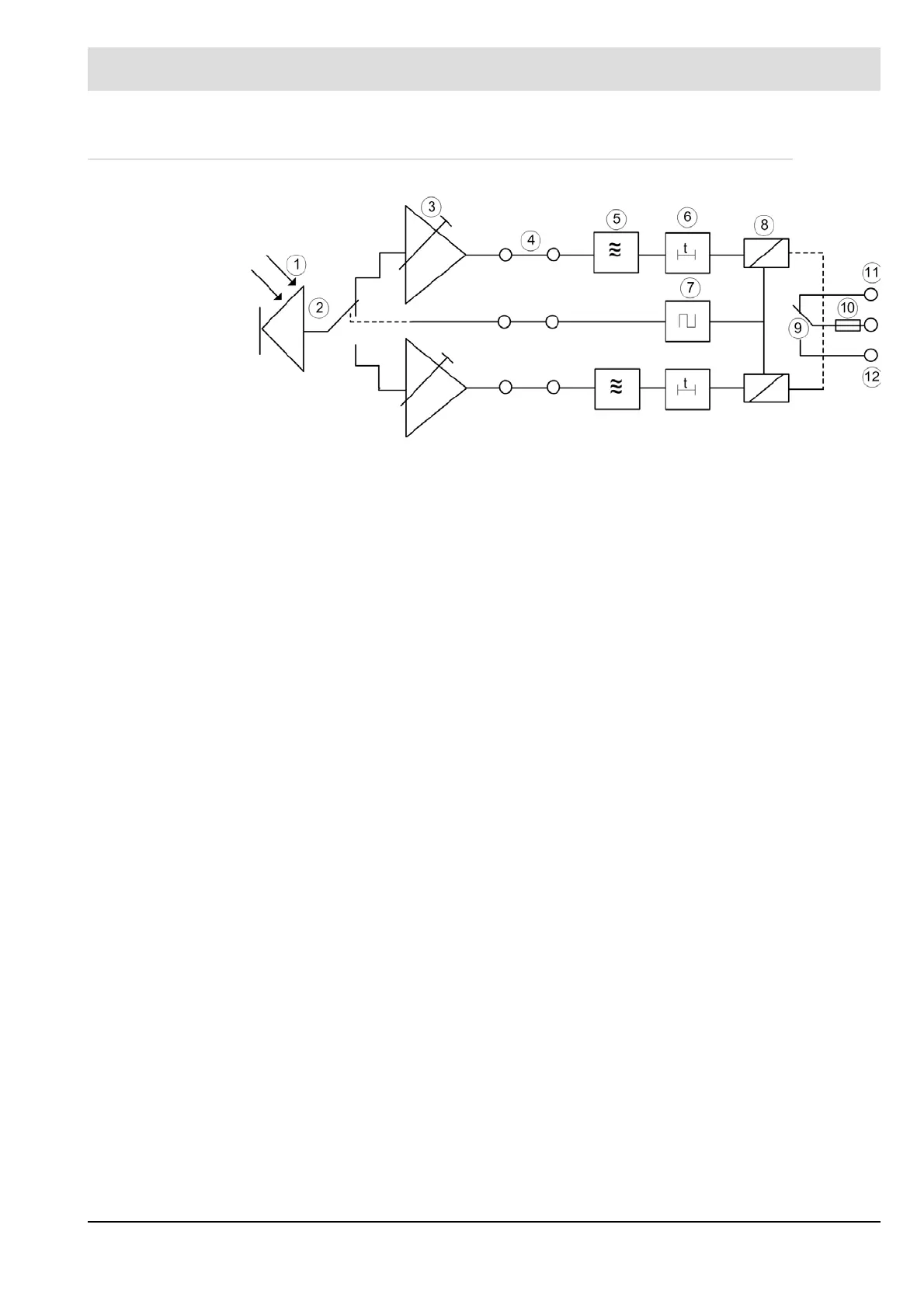
Fig. 4-1 Connecting diagram in principle - flame monitoring
Flame monitoring
The optical flame scanner converts the pulsing radiation parameters in a electrical signal by
means of a semiconductor sensor (1) (IR or UV). Subsequently only the flickering - i.e. the al-
ternate ratio of flame radiation - is processed. The signal is processed after a multiplexer (2)
using two channels.
The sensor signal’s sensitivity of the amplitude is set via DIP switches (3). The DIP switches
will be found on the circuit board inside the flame scanner’s housing.
The digitised signal is transferred via a shielded cable (4) to the reader.
The flame monitor calculates the signal’s time sequence (5).
The frequency calculation’s transferring range allows a signal sweep between 7 ... > 170 Hz
at which power frequency signals of 50 Hz or 60 Hz and the harmonised of them are ignored.
This happens sliding to the actual mains frequency.
After this the flame intensity is calculated (6). Two relays (8) output the result via the NO of
the output contacts (9) as the flame signal (12).
NC offers an indicator signal (11).
An internal fuse (10) secures the output contacts against fusing.
Self-monitoring function
A dynamic self-monitoring function (7) monitors if both processing channels are working prop-
erly. In fault condition the output relays are switched OFF by this function.
Information on the status
An LED display shows the status of the flame monitor - RT and GN for Flame OFF and ON,
YE flame intensity. Additionally flame intensity is displayed via a 0 ... 20 mA current loop as a
non-fail safe information. With a measuring cable the flame radiation’s amplitude is measura-
ble as an electronic signal. It may be read with a standard, digital voltmeter according to
EN 61010.
Secure Separation
The circuit is fed by mains. Output contacts may be used with mains. The power pack in the
F152 an the flame relay circuit meet the requirements of protective separation.