32
5 Commissioning
5.3.3 Testing the Functions
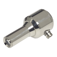
Measurement of the signal voltage and the flame sensor
Flame radiation may be measured between the blue wire (ground) and the pink wire (meas-
uring line) of the sensor’s connecting cable. Therefore a standard measuring instrument e. g.
hand-held multi-meter according to EN 61010 with a measuring resistor > 5 Mmay be used.
The measured voltage may lie in a range between a few mV up to 0,3 VAC with FFS08 UV
and up to 3 VAC by the other types.
NOTICE
The measuring output is intended for commissioning and maintenance.
A permanent connection of a measuring device is not intended.
In the following table, values are shown at which point the flame sensor interprets pending sig-
nals as flame signals.
For an optimal suppression of background radiation the measured values should be signifi-
cantly smaller than the described values below after the burner is switched off.
For reliable flame detection at a stable signal a two-fold value should be good enough. If the
flame detection is not stable higher values may be necessary.
After opening the housing, FFS08 IR-1 and FFS07 offers the opportunity to modify sensitivity
with the help of DIP switches (see chapter 5.3.4 Set Sensitivity). According to this the mini-
mum value for the signal "flame ON" changes.
FFS08 UV does not offer this opportunity for safty reasons.
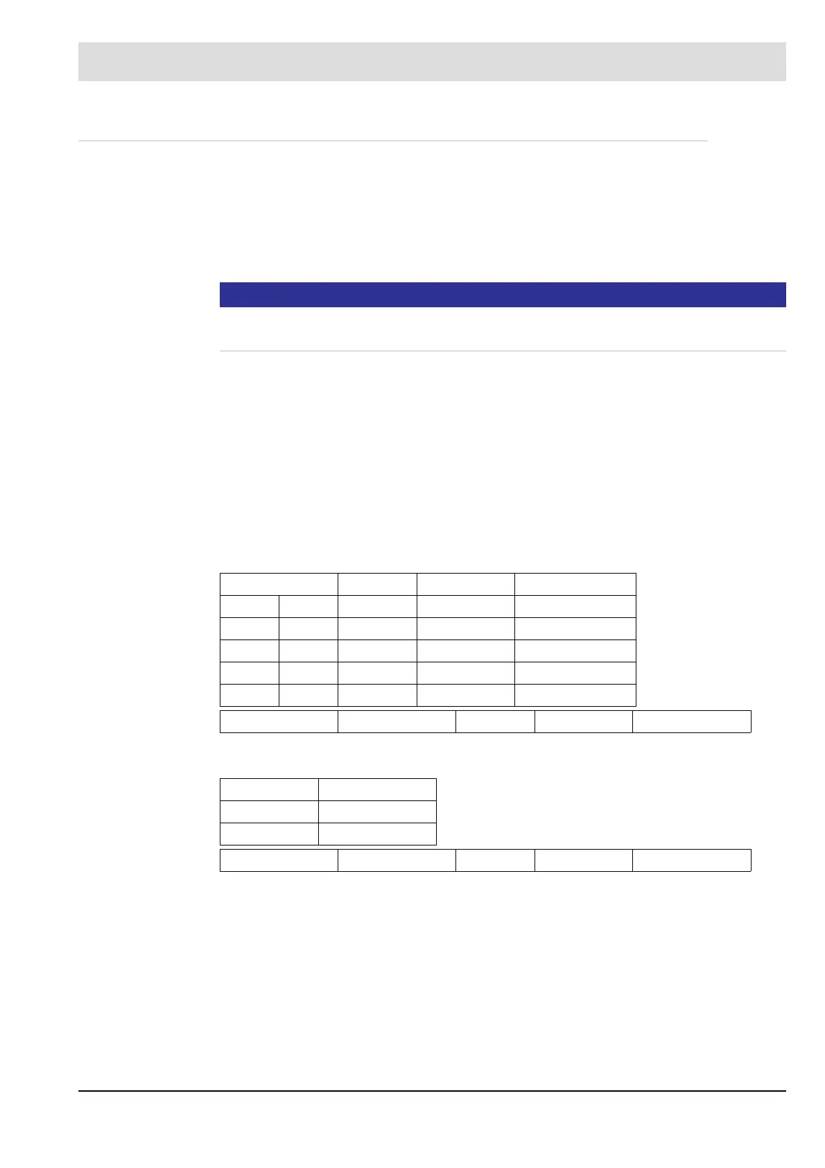
Flame scanners FFS08 IR-1, FFS07 IR-1, FFS07 UV-1, FFS07 UV-4
Ultraviolet Flame scanners FFS08 UV-1/UV-4
Switch Connection
Sx/1 Sx/2 Position pink/blue
OFF OFF 1 50 mV~
ON OFF 2 30 mV~ IR factory setting
OFF ON 3 20 mV~
ON ON 4 15 mV~ UV factory setting
Amibent noise without signal typical 1 (<2) mV~
Connection
pink/blue
25 mV~ factory setting
Ambient noise without signal typical 6 (<8) mV~