4
Selecting/Preparing Counter Location
Lancer does NOT recommend the use of shaved or
akeiceinthedispenser.
NOTE
4. Unit may be installed directly on countertop or on legs. If
installed directly on the counter, unit must be sealed to the
countertop with an FDA approved sealant. If an icemaker is
to be mounted on top of dispenser, do not install dispenser
on legs.
NSF listed units must be sealed to the counter or have
four (4) inch legs installed.
NOTE
5. Select a location for the remote carbonator, syrup pumps,
CO
2
tank, syrup containers, and water lter (recommended).
6. U s i n g C o u n t e r C u t o u t T e m p l a t e p r o v i d e d , c u t o u t r e q u i r e d
opening for the water, syrup, and CO
2
lines in the designated
dispenser location.
7. In order to facilitate proper dispenser drainage, ensure that
the dispenser is level, front to back and side to side. Place a
level on the top of the rear edge of the dispenser. The bubble
must settle between the level lines. Repeat this procedure
for the remaining three sides. Level unit if necessary.
For optimum performance place the unit at a 0° tilt. The
maximum tilt is 5°.
The dispenser should only be installed in a location
where it can be overseen by trained personnel
NOTE
1. Select a level, well ventilated location that is in close
proximity to a properly grounded electrical outlet, within ve
(5) feet (1.5 m) of a drain, a water supply that meets the
requirements shown in the Specications section found on
pages 4-6, away from direct sunlight or overhead lighting,
and has sucient clearance for air circulation.
2. Sucient clearance must be provided, if an ice maker is not
installed, to allow lling ice compartment from a ve gallon
bucket (a minimum of 16 inches is recommended).
3. The selected location should be able to support the weight of
the dispenser, ice and possibly an icemaker being installed
after counter cut out is made. Total weight (with icemaker) for
this unit could exceed 800 pounds (363.6kg).
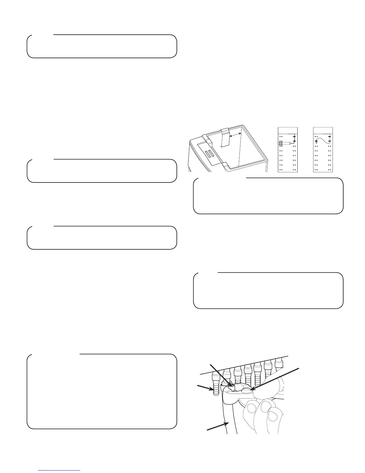
Installing an Icemaker (if necessary)
Wheninstallinganicemakeronthedispenser,usea
bin thermostat to control the ice level (see below). This
will prevent damage to the dispensing mechanism. The
bracketformountingathermostatislocatedintheice
bin. During the automatic agitation cycle and while
dispensing ice, ensure there is adequate space be-
tween the top of the ice level and the bottom of the
icemakersotheicecanmovewithoutobstruction.
Contactyouricemakermanufacturerforinformation
on a suitable bin thermostat.
! ATTENTION
Failure to use an ice bin thermostat will not only void
your IBD’s warranty but will result in the inability to
control the level of ice in the ice bin which can cause
damage to your dispenser.
! ATTENTION
1. Install the icemaker per manufacturer specications. Points
of consideration include drainage, ventilation, and drop
zones.
2. An adapter plate is required when installing an icemaker.
Contact your Sales Representative or Lancer Customer
Service for more information.
3. A bin thermostat is required in order to control the level
of ice in the dispenser (Refer to ATTENTION to the left).
Contact your icemaker manufacturer to obtain the correct bin
thermostat.
4. Bin thermostat should be a minimum of 2” below the top
edge of the dispenser. The preferred location of the bin
thermostat is on the left side wall.
5. Ensure the icemaker is installed properly to allow for removal
of the Merchandiser.
6. Ensure manual ll is accessible.
7. Clean and maintain icemaker per manufacturer’s
instructions.
4”
Attach Bin Stat Bracket As Shown Recommended Bin Stat Attachment
Bulb Tube
Dispenser Installation
The installation, and relocation if necessary, must
becarriedoutbyqualiedpersonnelwithup-to-date
knowledgeandpracticalexperience,inaccordancewith
current regulations.
NOTE
1. Remove the cup rest, drip tray, splash plate, merchandiser,
and top cover from the unit.
2. Route appropriate tubing from the water source to the plain
water inlet at the front of the unit and connect tubing to inlet
using the oetiker pliers and ttings,(see Plumbing Diagrams
on the front of the unit or on page 12 for reference).
A
B
C
A. Oetiker Pliers
B. Fitting
C. Tubing
D. Syrup/Water Inlet
D

 Loading...