F-1
F: Typical TTL-RS232 Circuits
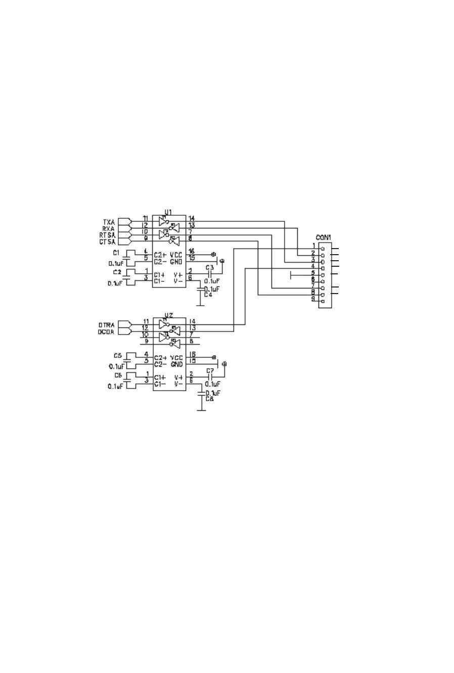
The following figures demonstrate typical TTL-to-RS232 conversion circuits.
Figure F-1: TTL-RS232 (DB-9) Circuit
Note: If you need just the DTR and DCD or RTS and CTS signals, you can
use only one Max232 chip.
Max232
Tx
DCD
Rx
DTR
GND
RTS
CTS
(DTE Configuration)
Max232
Circuit consists of:
- 2 Max232 compatible chips
- 8 capacitors
- 1 DB-9 connector
DB-9
male