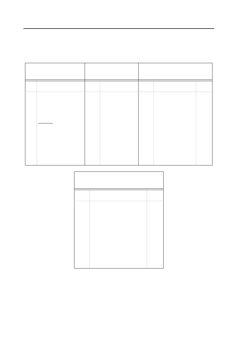
CoBox-Mini100 Connectors
4-3
The Embedded Integration Kit includes the CoBox-Mini100 embedded device server.
Refer to the following table for a listing of its pinouts.
*For Ethernet connection, either CON2 or CON3 should be used. The use of CON2 is
recommended for harsh and noisy environments.
**LED4 indicates 10M network speed, and LED5 indicates 100M network speed.
Both LED4 and LED5 can be used when either CON2 or CON3 is used.
Table 4-1: CoBox-Mini100 Connector Pinouts
CON1
TTL Serial Port
CON4
TTL Serial Port
*CON3
10/100BASE-T Connector
Pin Signal Pin Signal Pin Signal RJ45
1
2
3
4
5
6
7
8
9
10
+5VDC
GND
TxA (output)
RxA (input)
RESET
(pull low to
reset)
DCDA (input)
LED1 (Channel 1)
LED2 (Channel 2)
LED3 (Diagnostics)
+5VDC (for LEDs 1-3)
1
2
3
4
5
6
7
8
9
10
DTRA (output)
GND
RxB (input)
TxB (output)
CTSA (input)
CTSB (input)
RTSA (output)
DTRB (output)
DCDB (input)
RTSB (output)
1
2
3
4
5
6
7
Tx+
Tx-
Rx+
Rx-
Decoupling (Shield)
LED4 (Link)**
+5VDC (for LED4)
1
2
3
6
*CON2
10/100BASE-TX Connector
Pin Signal RJ45
1
2
3
4
5
6
7
8
9
10
11
Tx+
Tx-
Rx+
Decoupling
Decoupling
Rx-
Decoupling
Decoupling
Decoupling (Shield)
LED5 (speed 100MBit)**
+5VDC (for LED5)
1
2
3
4
5
6
7
8