Test Bed CoBox-Mini100
4-6
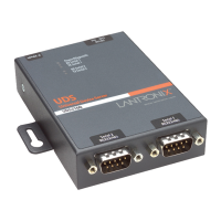
Test Bed Connectors
The CoBox-Mini100 test bed has five external connectors: CON4 (a 10/100Base-TX RJ45
connector), CON7 (serial port 1 or Channel 1), CON8 (serial port 2 or Channel 2), CON1
(a 9-30 VDC power supply connector).
Table 4-3: CoBox-Mini100 Test Bed Connector Pinouts
CON4
10/100Base-TX
(RJ45)
CON7
Serial Port
(Channel) 1
a
a. “CON7 Serial Port (Channel) 1” is also designated as “A”.
CON8
Serial Port
(Channel) 2
b
b. “CON8 Serial Port (Channel) 2” is also designated as “B”.
Pin Signal Pin Signal Pin Signal
1
2
3
4
5
6
7
8
Tx+
Tx-
Rx+
Decoupling
Decoupling
Rx-
Decoupling
Decoupling
1
2
3
4
5
6
7
8
9
DCDA (input)
RxA (input)
TxA (output)
DTRA (output)
GND
None
RTSA (output)
CTSA (input)
None
1
2
3
4
5
6
7
8
9
DCDB (input)
RxB (input)
TxB (output)
DTRB (output)
GND
None
RTSB (output)
CTSB (input)
None