CrossLink-NX Evaluation Board
User Guide
© 2019-2020 Lattice Semiconductor Corp. All Lattice trademarks, registered trademarks, patents, and disclaimers are as listed at www.latticesemi.com/legal.
All other brand or product names are trademarks or registered trademarks of their respective holders. The specifications and information herein are subject to change without notice.
26 FPGA-EB-02028-1.3
*Note: 3.3 V and 5 V provide the power to the Raspberry Pi board when JP3 and JP4 are installed. When JP3 and JP4 are not
installed, Raspberry Pi needs its own 3.3 V and 5 V power.
When connecting directly to a Raspberry Pi board, depending on the individual setup, there may need to be an adapter
to avoid mechanical interference between the two boards. A generic 40-pin (2×20), 100-mil spacing header extender
serves this function. Alternately, the two boards can be connected by a length of ribbon cable with 2×20 connectors on
either end.
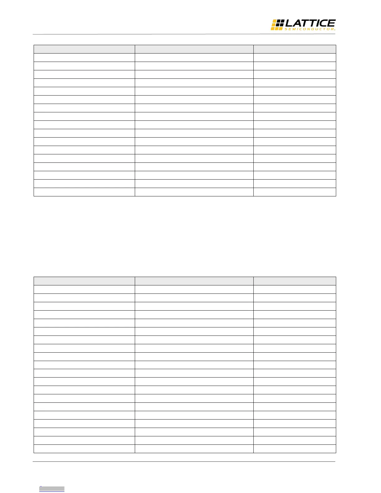
8.4. Camera Connector
Table 8.4. Camera CN1 Connector Pin Connections
Downloaded from Arrow.com.Downloaded from Arrow.com.Downloaded from Arrow.com.Downloaded from Arrow.com.Downloaded from Arrow.com.Downloaded from Arrow.com.Downloaded from Arrow.com.Downloaded from Arrow.com.Downloaded from Arrow.com.Downloaded from Arrow.com.Downloaded from Arrow.com.Downloaded from Arrow.com.Downloaded from Arrow.com.Downloaded from Arrow.com.Downloaded from Arrow.com.Downloaded from Arrow.com.Downloaded from Arrow.com.Downloaded from Arrow.com.Downloaded from Arrow.com.Downloaded from Arrow.com.Downloaded from Arrow.com.Downloaded from Arrow.com.Downloaded from Arrow.com.Downloaded from Arrow.com.Downloaded from Arrow.com.Downloaded from Arrow.com.