LAUNCH Electronic Two-post User’
11
4 Hydraulic and Electrical System of the Equipment
4.1 Hydraulic System of the Lift
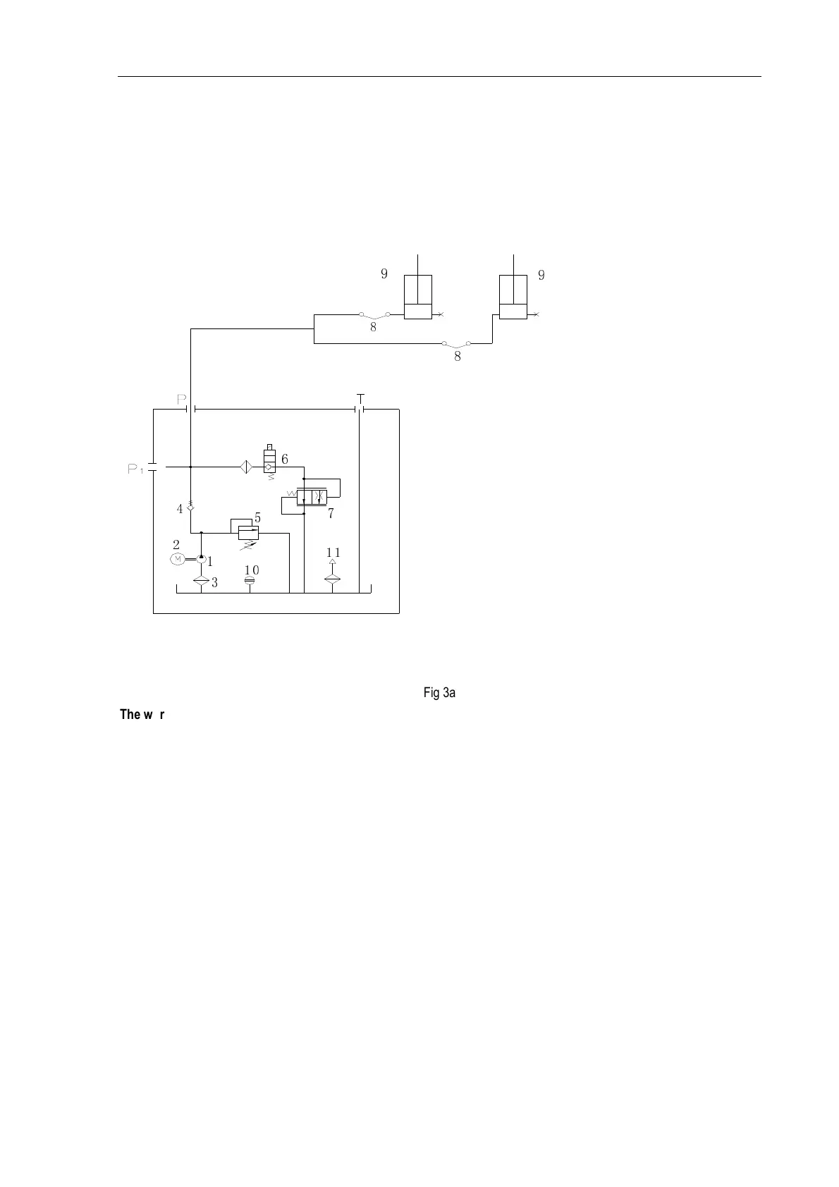
Diagram of the hydraulic system of clear-floor 2-post lift
11
2
3
1
4
10
5
7
6
8
9
8
9
Fig 3a
The working principle of the hydraulic system is as
follows:
When the UP button is pressed, the motor is started,
driving the oil pump, sucking the hydraulic oil from the oil
tank into the oil cylinder 9, forcing the piston rod move. At
this time, the safety valve 5 is closed, and the Max working
pressure is already adjusted before ex-factory. The safety
valve can ensure the capacity of the rated load, but when
the pressure in the system exceeds the limit, automatically
overflow will be happened inside safety valve to protect the
hydraulic system. Release the UP button to stop the oil
supply and the lifting will stop. For lowering, press and hold
the UNLOCK button, the electromagnetic safety lock
mechanism will be released, meanwhile press the DOWN
button, the solenoid valve 6 is actuated, the hydraulic oil
flows back from the hydraulic cylinder into the oil tank
through the solenoid valve 6 and flow-control valve 7, and
the lift starts the lowering.
1- Gear pump, 2- Motor, 3- Oil filter, 4- Check-valve, 5- Safety valve, 6- Solenoid valve,
7- Servo flow-control valve, 8- Hose, 9- Hydraulic cylinder, 10- Level gauge, 11- Air filter
(C) Diagtools; www.diagtools.eu; diagtools@diagtools.lv; Pernavas 43A, Riga, Latvia, LV-1009; +37129416069