LAUNCH Electronic Two-post User’
24
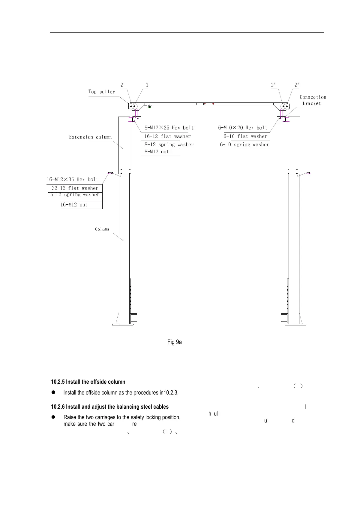
Diagram of column, extension column and top beam
8-M12×35 Hex bolt
16-12 flat washer
8-M12 nut
8-12 spring washer
6-M10×20 Hex bolt
6-10 flat washer
6-10 spring washer
Top pulley
2 1 1″ 2″
Column
16-M12×35 Hex bolt
32-12 flat washer
16-12 spring washer
Extension column
16-M12 nut
Connection
bracket
Fig 9a
10.2.5 Install the offside column
Install the offside column as the procedures in10.2.3.
10.2.6 Install and adjust the balancing steel cables
Raise the two carriages to the safety locking position,
make sure the two carriages are of the same height
from ground. for TLT235SBA
、
TLT235SBA
(
E
)、
TLT240SBA models, route the steel cables as Fig. 9b
shows ,for TLT240SCA
、
TLT235SCA
(
U
)
models,
route the steel cables as Fig9c shows..
Adjust the tension of cables through the adjustment
nuts on each end of steel cable. The steel cables
should be tight in equal tension. Each steel cable
should be ensured in the pulley when adjusting tightly,
otherwise the steel cable will be damaged.
(C) Diagtools; www.diagtools.eu; diagtools@diagtools.lv; Pernavas 43A, Riga, Latvia, LV-1009; +37129416069