Rev: 03.19.21 Page 27 CCD-0004319
BA
G
H
C D
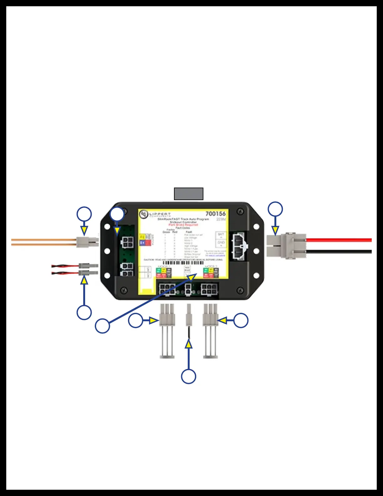
Fig. 35
F
E
Harness Connections for Auto-Program Motorized and Towable Controllers
1. Route and attach the switch harness (Fig. 35A) from the controller (Fig. 35B) to where the switch will be
mounted.
2. Route and attach the motor 1 harness (Fig. 35C) and motor 2 harness (Fig. 35D) from the controller to
the corresponding slide-out motors.
NOTE: When identifying motor 1 and motor 2, refer to figure 24.
3. For Motorized units only: Route and attach the park input harness (Fig. 35E) from the controller to
the park brake signal source, if applicable.
NOTE: Towable control does not have the park brake receptacle and does not require signal from park
brake.
4. Route and attach the proper gauge wire (Fig. 35G) from the controller to the 12V DC battery.
5. Optional for Lippert OneControl integration: Attach the Canbus data harnesses to the 2 CAN
receptacles (Fig. 35H).
NOTE: Refer to Wiring Diagram (Fig. 37) for additional system wiring information.


 To Next Page