Rev: 03.19.21 Page 28 CCD-0004319
Fig. 36
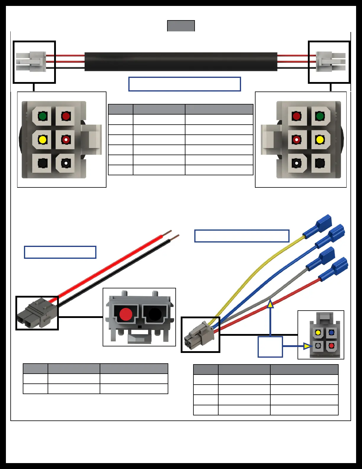
Pin Color What It Controls
1 Green Channel 1 Sensor
2 Yellow Channel 2 Sensor
3 Black Ground Sensor
4 Red Power Sensor
5 Red/White Motor Lead 2
6 Black/White Motor Lead 1
Pin Color What It Controls
1 Black Ground
2 Red Power
Pin Color What It Controls
1 Gray Fault Code LED
2 Red Switch Power
3 Yellow Switch Out
4 Blue Switch In
NOTE: If the slide-out operation rocker switch is not supplied by Lippert Components, the gray wire on the
4-wire switch harness is not used.
Rocker Switch Harness
Power Harness
Controller-to-Motor Harness
See
NOTE
Pinout Diagram for Motorized and Towable Controllers