Rev: 03.19.21 Page 22 CCD-0004319
A
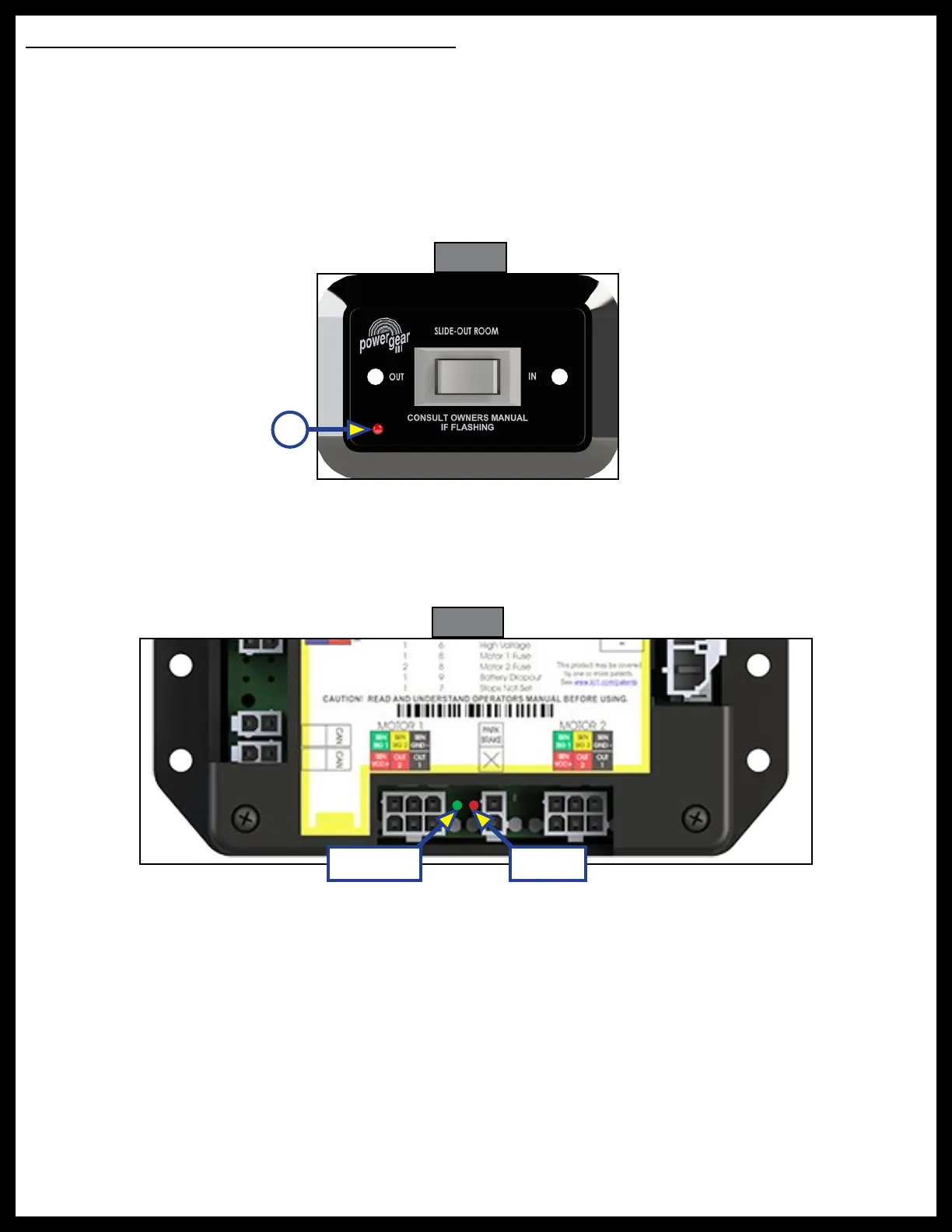
Fig. 28
Fig. 29
Auto-Program Motorized or Towable Controller
This controllers have the ability to detect and display several faults. When a fault is detected, the slide-out
room movement will stop and two different LEDs (Fig. 29) on the controller will flash in a pattern.
1. The Fault Code LED (Fig. 28A) on the rocker switch will flash RED a number of times corresponding
to the number of red flashes on the controller (Fig. 29A). Refer to Controller Fault Codes chart to best
determine what caused the fault.
NOTE: Not all rocker switches contain fault indicator LEDs. For best results when reading fault codes, refer
to the controller's Fault Code LED scheme (Fig 29) and Controller Fault Codes chart.
2. The Motor LED (Fig. 29B) on the controller will flash GREEN a number of times corresponding to which
motor had the associated fault.
NOTE: For example, two GREEN flashes and four RED flashes means there is a motor fault on motor 2.
B - Green
A - Red