Rev: 03.19.21 Page 12 CCD-0004319
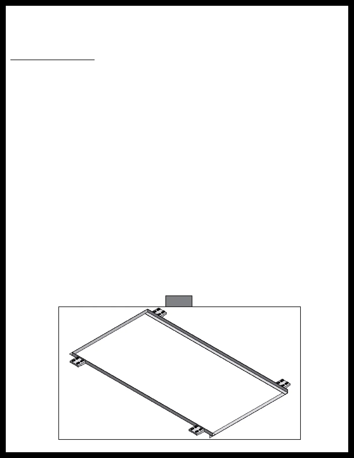
Fig. 12
Installation
The instructions are for a one slide-out located on either the roadside or curbside of the unit (Fig. 8).
The instructions cover the configurations of controllers and user interfaces: auto-program motorized or
towable controllers paired with rocker switch.
Mechanical Components
1. Install Lippert Components-approved floor rollers. Consult roller manufacturer for proper installation
procedures and location.
2. For sealing the screws used to attach end brackets, Lippert Components recommends RTV Silicone,
rubber gaskets, or closed cell foam gaskets. DO NOT use any type of sealant putty as this can intrude
into the mechanism and possibly cause the system to malfunction.
Using a Drill Fixture
NOTE: It is recommended that the OEM create a drill fixture to aid in installation.
A drill fixture (Fig. 12) is used to pre-drill the mounting holes for the end brackets and maintain even spacing
between the upper and lower gear rack arms.
NOTE: Even spacing between the gear rack arms and the location of the end brackets is critical for proper
operation of the slide-out. Drill fixtures are reusable from system to system. Drill fixtures are not
supplied with the system and must be purchased from Lippert Components to aid in assembly and
reduce installation time.
A. Position the drill fixture so that the bottom flange of the fixture is pulled up against the bottom of
the slide-out.
B. Move the drill fixture out so that it is up flush against the outer slide-out flange.
C. Drill all 16 holes (four per bracket) with a #25 drill bit.
NOTE: During normal operation of this system, there is a possibility that the gear racks could come in
contact with the slide box. At manufacturer's discretion, paint protection film may be used to
prevent rubbing or scratches to any slide box surface. This protective film may also be added after
paint is applied.
D. Place the slide mechanism up to the side of the slide-out and secure end brackets with #10 button
or pan head screws torqued to 40-50 in-lbs.
E. Repeat steps A-E for the other side of the slide-out.
3. Place slide-out box into slide-out opening and push until the mounting flange meets the exterior wall.


 To Next Page