Calibration
PHOTON
+
System Guide 30
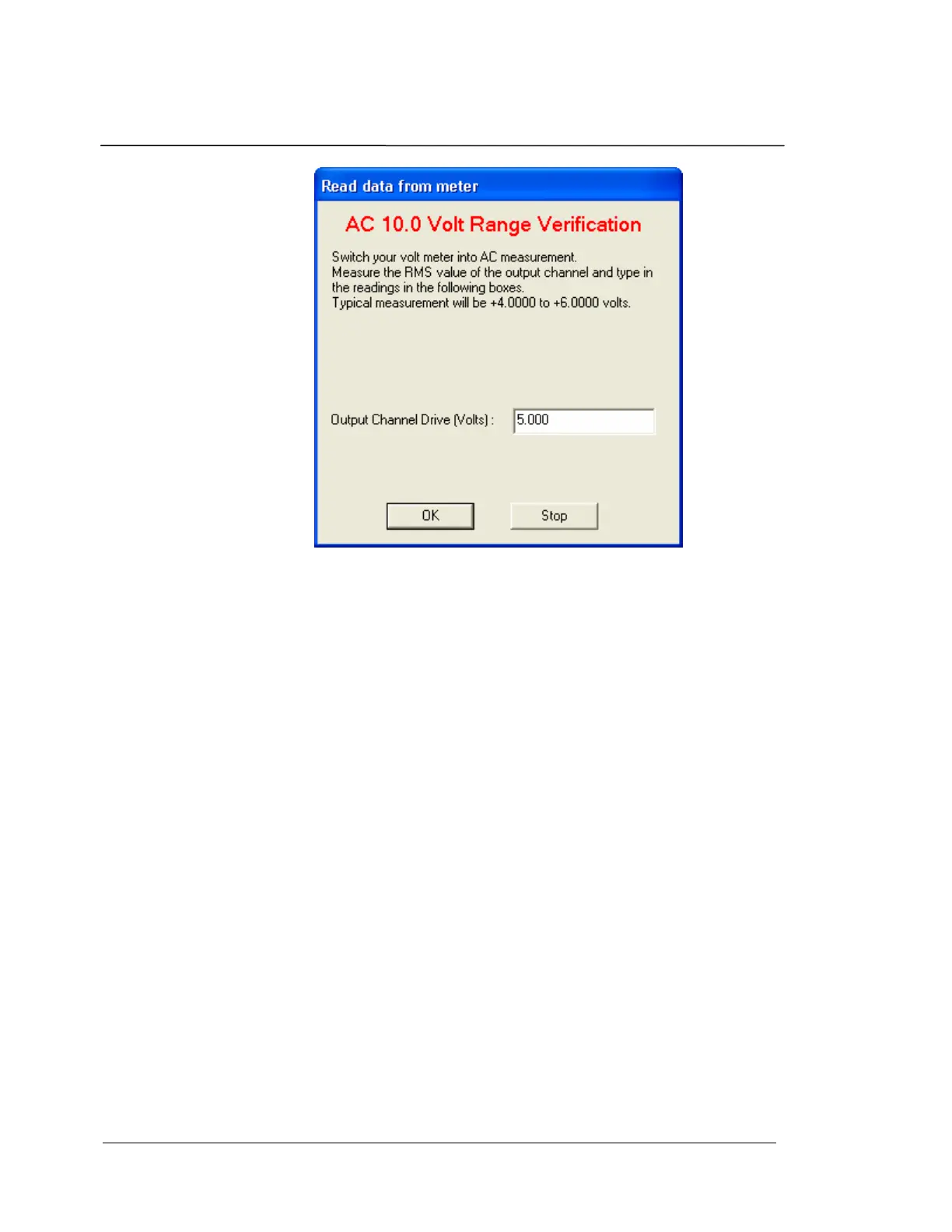
AC Measurement for the Gain Validation
After validation, both the offset and gain error should be within
tolerance.
The pass/no-pass tolerance used during the validation is:
10 volt range: 1% of the Full Scale
1.0 volt range: 2% of the Full Scale
Low-voltage Range Calibration
The PHOTON
+
has low voltage input ranges of 0.1 V and 0.01 V.
Therefore, the Output Channel and Input Channel Calibrations described
previously will be repeated at these low voltage input ranges.
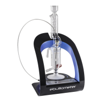
At the start of the Low-voltage Range Calibration you will be asked to
connect the Attenuator Module to your cable harness as shown in the
image below. Connect the PHOTON
+
Output Channel to the BNC labeled
“Input” on the Attenuator Module then connect the BNC labeled
“Output” to your cable harness.
Power up the Attenuator Module and wait for at least 10 minutes prior to
continuing. If required, record environmental parameters such as
pressure, humidity etc…