11. Video Signal Waveform Display
11-5
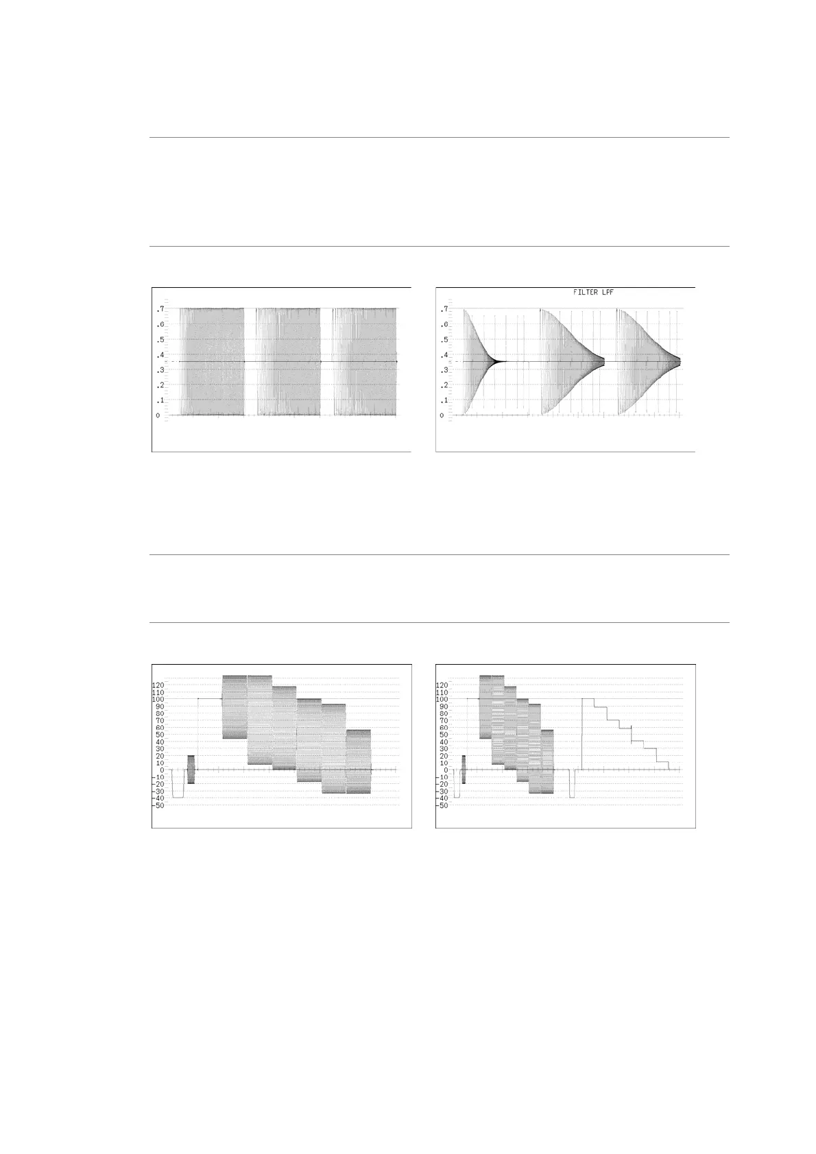
• When COLOR MATRIX is set to Y,CB,CR; GBR; or RGB
Settings
FLAT: This filter has a flat frequency response over the entire bandwidth of the input
signal. This is the default setting.
LOW PASS: This filter is a low-pass filter with the following frequency responses:
Attenuation of 20 dB or more at 20 MHz when the input signal is HD-SDI
Attenuation of 20 dB or more at 3.8 MHz when the input signal is SD-SDI
FILTER = FLAT FILTER = LOW PASS
Figure 11-5 Component signal filter displays
• When COLOR MATRIX is set to COMPOSIT
Settings
FLAT: Only the pseudo-composite signal is displayed. This is the default setting.
FLAT+LUM: The pseudo-composite signal and the luminance signal are displayed side by
side.
FILTER = FLAT FILTER = FLAT+LUM
Figure 11-6 Pseudo-composite signal filter display


 To Next Page