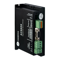
Hardware Installation Manual of Easy Servo
17
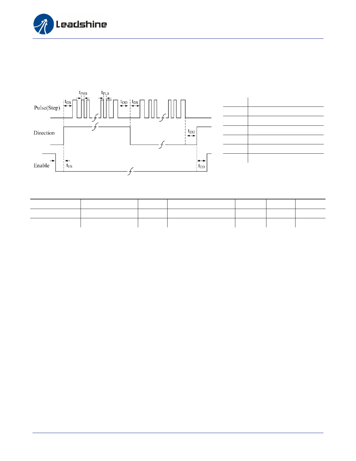
Control Signal Setup Timing
To make a reliable operation, the ES drive requires the control signals to meet the setup time
requirements as follows. Otherwise losing of steps may happen.
Current Control Detail
Leadshine’s hybrid servo motor is integrated with a high-resolution 1,000-line optical incremental
encoder. That encoder can send the real-time shaft position back to the hybrid drive. Like traditional
servo controls, the drive can automatically adjust the output current to the motor. The output
current ranges between the holding current and the close-loop current. When there is no pulse sent
to the drive, the ES goes into idle mode and the actual motor current is determined by the holding
current percentage (similar to “ idle current” of open loop stepper drives). In normal working mode,
the ES monitors the actual shaft position all the time. The current outputted to the motor changes
dynamically based on the tracking error between the actual position and the commanded position.
Low holding current can reduce motor heating however also reduces the holding torque which is
used to lock the motor shaft at standstill. It is recommended to determine the holding current by
whether or not there is big vibration at start-up and how much lock torque is required, based on your
actual applications.
Control Signal Setup Time
Drive Frequency t
DS
t
PHS /
t
PLS
t
DD
t
ES
t
ED
ES-D508 / 2306 200K >50uS >2.5us >50uS >50ms >50ms
ES-D808 / 1008 200K >50uS >2.5us >50uS >50ms >50ms
Symbol
Description
t
DS
Direction Setup Time
t
PHS
Pulse High Level Setup Time
t
PLS
Pulse Low Level Setup Time
t
DD
Direction DelayTime
t
ES
Enable Setup Time
t
ED
Enable Delay Time