1
321070
A (mm) B (mm) C (mm)
198 157 27
B
A C
1
2
10
3 4 5 6
9
8
7
14
15
16
17
11 12 13
18 19
20 21
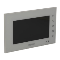
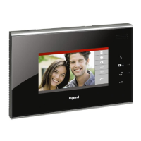
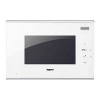
D45 System
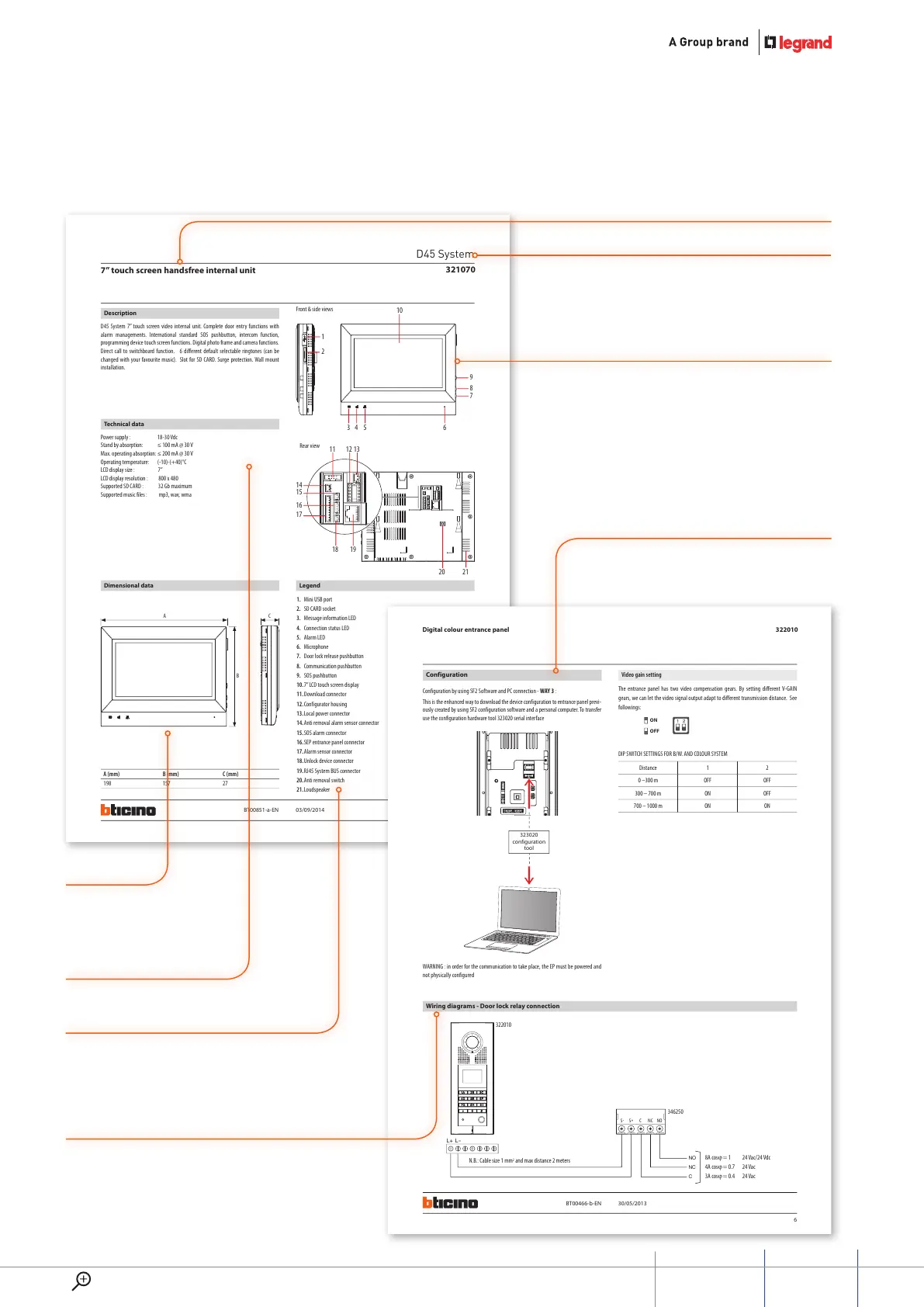
7” touch screen handsfree internal unit
BT00851-a-EN 03/09/2014
Description
D45 System 7” touch screen video internal unit. Complete door entry functions with
alarm managements. International standard SOS pushbutton, intercom function,
programming device touch screen functions. Digital photo frame and camera functions.
Direct call to switchboard function. 6 different default selectable ringtones (can be
changed with your favourite music). Slot for SD CARD. Surge protection. Wall mount
installation.
Power supply : 18-30 Vdc
Stand by absorption: ≤ 100 mA @ 30 V
Max. operating absorption: ≤ 200 mA @ 30 V
Operating temperature: (-10)-(+40)°C
LCD display size : 7”
LCD display resolution : 800 x 480
Supported SD CARD : 32 Gb maximum
Supported music files : mp3, wav, wma
Dimensional data Legend
1. Mini USB port
2. SD CARD socket
3. Message information LED
4. Connection status LED
5. Alarm LED
6. Microphone
7. Door lock release pushbutton
8. Communication pushbutton
9. SOS pushbutton
10. 7” LCD touch screen display
11. Download connector
12. Configurator housing
13. Local power connector
14. Anti removal alarm sensor connector
15. SOS alarm connector
16. SEP entrance panel connector
17. Alarm sensor connector
18. Unlock device connector
19. RJ45 System BUS connector
20. Anti removal switch
21. Loudspeaker
Front & side views
Rear view
Technical data
6
322010
1 2
ON
OFF
S-
S+
C
NC
NO
L+ L
-
NO
NC
C
322010
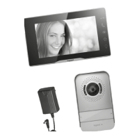
346250
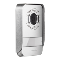
Digital colour entrance panel
Distance 1 2
0 –300 m OFF OFF
300 – 700 m ON OFF
700 – 1000 m ON ON
This is the enhanced way to download the device configuration to entrance panel previ-
ously created by using SF2 configuration software and a personal computer. To transfer
use the configuration hardware tool 323020 serial interface
Configuration by using SF2 Software and PC connection - WAY 3 :
WARNING : in order for the communication to take place, the EP must be powered and
not physically configured
The entrance panel has two video compensation gears. By setting different V-GAIN
gears, we can let the video signal output adapt to different transmission distance. See
followings:
DIP SWITCH SETTINGS FOR B/W. AND COLOUR SYSTEM
Configuration
Wiring diagrams - Door lock relay connection
323020
configuration
tool
Video gain setting
N.B.: Cable size 1 mm
2
and max distance 2 meters
8A cosϕ = 1 24 Vac/24 Vdc
4A cosϕ = 0.7 24 Vac
3A cosϕ = 0.4 24 Vac
BT00466-b-EN 30/05/2013